Vintage gear can develop a number of problems. There is already a lot of material available online about replacing electrolytic capacitors, which heat and age can dry out causing them to lose capacitance. Unsoldering capacitors is fiddly work, really needs a good quality desoldering station, and can take a lot of time if there are lots of capacitors to change (replace with higher temperature rating and higher voltage if there is space...) Backlit LCD displays are another common problem, where the electroluminescent backlight drivers fail over time, and the LED backlights gradually seem to go dim. If you can find OLED replacements then these are arguably the best, but I haven't been able to find out much about the real-world long-term life of them - after all, 90s gear is nearly 30 years old! And then there are 3.5 inch floppy disk drives - particularly the ones which use belts instead of direct drive. It seems that old drive belts go loose, or go sticky, or go brittle, and all of these tend to result in a floppy drive that doesn't work.
I've been gradually replacing the backlit displays and floppy drives on my vintage gear. To be more accurate, I mean 'what used to be backlit' displays. When you start replacing displays, you quickly discover that the difficulty of doing it varies enormously. Some synthesizer expander modules (the Yamaha TX7, for example) are very easy, whilst some keyboard workstations can require quite extensive amounts of disassembly. Here's a link to a pretty detailed description from a blog post describing the process for a Korg Wavestation: https://jaryic.livejournal.com/11778.html . As it says, 'not for beginners'. I couldn't find any way to backlight my Roland TR-505, though, so if anyone has any ideas, just let me know...
Floppy drives tend to be easier to replace, but there are sometimes complications. For example, the Yamaha SY99 uses a 26 pin floppy drive interface cable, rather than the more usual 34 pins, and that has long been a topic of much discussion on the relevant Yamaha forums. Most of the better companies that sell floppy drive emulators are well aware of this complication, and have their own reliable, verified and tested adapters.
My own description of the pinouts of the 26 and 34 pin connectors is still available on the Interweb: http://www.martinruss.com/sy99adapter.html Then there is also my description of replacing a failed SY99 floppy with the long-discontinued official Yamaha replacement, complete with Yamaha adapter board: http://www.martinruss.com/sy99.html This article is probably rapidly becoming 'vintage' in its own right!
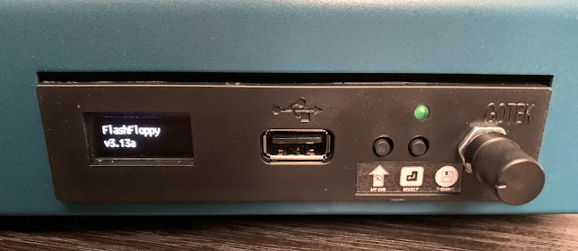
But my Yamaha RM1x floppy drive proved to be a different type of challenge. The floppy drive is accessed via the front panel of the RM1x, whilst the main control surface of the RM1x is the top surface.
When the only control on the floppy drive was the 'Eject' button, and the writing on the floppy label was easy to read as it ejected, this was fine, but for modern floppy emulators, there are more controls, and a display. The simple 7-segment LEDs are not my recommendation - OLEDs which show file names are much better, if a little tiny. But the display is on the front of the floppy emulator...
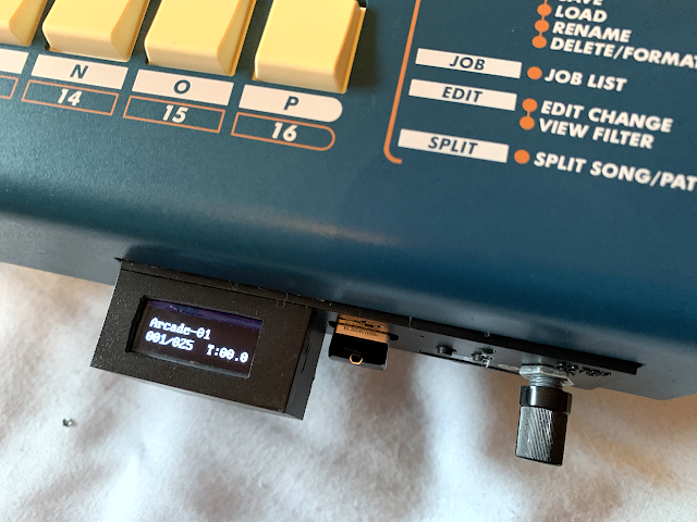
This means that the OLED display of the floppy emulator is not easy to see when you are using the RM1x. You only need to bend down and lean back a few times so that you can see the display before you realise that it is very awkward. So I moved the display so that it was easy to read when you are using the top 'control' surface of the RM1x!
But, first things first. I got my floppy disk emulators from CPMagneticMedia on ebay.co.uk: https://www.ebay.co.uk/usr/cpmagneticmedia , who are very knowledgable, and have a wide range of floppy emulators, backlit LCDs, and lots of other useful stuff for customisers/upgraders, etc.
The first thing I did when I had the floppy emulator installed and working was to remove it, open it up and thus void the warranty! The OLED was held in place with hot glue, which is easy to remove if you have a hot glue gun...
But before removing the OLED display, I got a 'potting box' of about the right size and worked out how much I needed to cut it down with my trusty Dremel...
Then I removed the OLED display (Carefully! They are very delicate - note the black foam used to hold it in place...) and removed the remaining hot glue with snipe nose pliers.
Then I cut the potting box to size and cut out a window in the top surface the correct size for the OLED display - using the existing hole in the floppy emulator as a guide.
One of the actions to keep doing when making mods like these is to check and re-check. So I now checked that the OLED, the mounting foam and the new potting box all fitted together nicely.
I then extended the four way cable to the OLED, so that I could push it through the hole in the floppy emulator front panel.
I then mounted the OLED display in the potting box, using the mounting foam and more hot glue, then glued the potting box to the floppy emulator front panel.
And from the top, things are a lot neater in appearance.
From the remains of the potting box, I then made a cover for the underside of the box, to hide the extender cable... and glued it in place.
The finished result looks very nice!
Now you can easily see the display when you are controlling the RM1x.
Full disclosure: before I extended the display into the potting box, I did explore using a prism to try and twist the display so it would be visible, but this suffered from the 'mirrors only swap one direction, not both' problem and I got reversed text on the display.
I would like to thank CPMagneticMedia for all their help with this project!
As with any mod, you are almost certainly going to invalidate warranties, and you may break rare or custom parts that are hard to find. So you do any mods at your own risk! Only do mods if you are confident and experienced.
Postscript
Some people have asked me if I could send them the FlashFloppy FF.CFG file for the drive, as well as the jumper settings. I did not buy a generic Gotek drive, flash it and configure it - I bought a custom RM1X-specific drive that was already flashed and pre-configured, with a rotary encoder and an OLED display.
If you want to use FlashFloppy on a generic Gotek drive, then the GitHub site is at:
https://github.com/keirf/FlashFloppy/wiki/FF.CFG-Configuration-File
---
If you find my writing helpful, informative or entertaining, then please consider visiting this link:


Fantastico!
ReplyDelete