Thursday 25 June 2020

Triple Flexible Routing Probabilistic Transposing Delay in Max For Live for Ableton Live

Sometimes, a MaxForLive device is right on the edge of not working, and normally I put it to one side for 'further investigation'. But every so often, an 'almost working' device is so cool that it goes along a different route: an experimental device with warnings. MIDIdelA3 is just such a device...

For a while now, I have been exploring the edge of the musical map that has 'Probability' on it, off to one side of a region called 'Generative'. But it wasn't until I combined probability with a much older topic, echoes, that things started to get really interesting. One of my very early echo effects was called 'Missing Echo', because it didn't put an echo on every note, and updating the concept with probability, as well as moving the delay into the MIDI domain, started to produce some useful results.

People have been playing around with echo and delay effects for a long, long time. One of the current 'leading lights' is Olafur Arnalds, an Icelandic multi-instrumentalist who has been using custom 'smart delay' software in live performance, and who recently collaborated with Spitfire Audio to release 'Stratus', a toolkit of software and a linked sample library that uses complex delays to augment live performance.

MIDIdelA3


MIDIdelA3 isn't complex, and it isn't anywhere near the functionality of Stratus, but it hovers at the edge of what my 2008 Macbook Pro can reliably accomplish in MaxForLive. It might be generously described as being 'far from perfect', and isn't really suitable for 'mission critical' use, but it is a fascinating glimpse into what is possible with MaxForLive. It has three identical processing sections, each with a delay, a transposer, a probability control, a velocity scaler and a loop switch. You can connect the three sections together in three different ways: in series, in parallel, and in a mix of serial and parallel. There are 20 memories, and a large rotary control that lets you select from those memories, so once you have set up the memories, then it can be used as a 'single control' device if you wish.

Setting up the memories sounds easy, but there's more to it than meets the eye. Having three different topological connections between the three sections is quite hard to get your head around, and the probability control has more effect that you might think, because when a note has an 80% chance of passing through a section, then that drops when it goes through a second section with 80% probability, and if it goes through a third section, then another 80% probability means that you aren't going to hear that triply-delayed note very often. Then there's the velocity scaling, which reduces the velocity of notes, and which is particularly important when you loop a section, because it keeps things stable, or almost does. Yep, this is one of those delays that can run away with itself...

Inside

I haven't used the MIDI Delay that Ableton include as one of the MaxForLive demos because it is too much like 'a maze of twisty little passages, all different'... Instead I have coded it myself using a different approach, and this probably explains why it 'almost' works - my programming is not very advanced, I'm afraid. But it does get close enough to being usable to be worth revealing, because I'm sure that there are better programmers out there who can improve on the concept...and like all of my software on MaxForLive.com, it is free and unencumbered by rights licensing restrictions.

The way that you are supposed to do operations on time-critical events is to time-stamp them as they arrive, and then work your way through a time-based list, so that they are dealt with in strict time order. If you look inside the Ableton MIDI Delay example MaxForLive code then that is exactly what you will find - and there's quite a lot of code in there...

I chose to do it using the much simpler 'cheat's' way. I used two 'pipe' objects, one for the MIDI Note Number values, and the other for the MIDI Velocity values. Normally, when time-stamping a pair of values like Note Number and Velocity, you would group them together as a single event, and give that pair of values a time-stamp. When using two separate pipe objects, then the Note Number becomes one event in a time-delay, whilst the Velocity becomes a different event in a different time-delay. You can probably see why this isn't a perfect solution! But, for 'quick and dirty', it kind of works, and it requires very little coding!

So for the three processing sections (Time Delay, Transpose, Probability, Velocity Scaling, and Looping) there are six pipe objects, arranged in pairs (Note Number, Velocity). These three sections are connected together using a set of 24 switches that do all of the routing for the three different ways that the three sections can be connected (serial, parallel, and a mix). The three connection diagrams look a little bit like the FM 'Algorithm' diagrams that the Yamaha DX7 had on its top panel, and they kind of show the same sort of routing, but nothing more than that.

Using it

Depending on the way that the three processing sections are connected, the basic explanation goes like this:


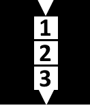
Connection 1 - the serial (top diagram) connection sends the MIDI messages through section 1 (and outputs delayed notes), then section 2 (and outputs delayed notes), then section 3 (and outputs delayed notes).


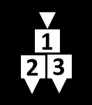
Connection 2 - the mix of serial and parallel connections (middle diagram) sends the MIDI messages through section1 and outputs delayed notes), and then through section 2 and 3 at the same time (in parallel) (and outputs delayed notes from both sections).


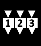
Connection 3 - the parallel (lower diagram) connection sends the MIDI messages through sections 1, 2 and 3 at the same time (and outputs delayed notes from all 3 sections.)

Each section has a separate Loop button, and the Velocity Scaling rotary control acts like the 'Feedback' control in an ordinary audio delay or echo effect. If the Velocity Scaling is set too high, then the processor will quickly become overwhelmed with too much data, and will stop working. This may cause strange noises, which may be loud! Please use the Loop buttons with care. If the device does become overwhelmed, then the 'All' button can be used to turn off any of the Loop buttons.

The Loop buttons can be turned on whilst the device is operating. So you can set up the controls, and then turn on looping for just one of the sections - this is very effective for creating rhythmic 'motifs' and other repeating sounds. The recommendation is that you normally have all of the Loop buttons set to Off, and turn one (or more) on to get a repeated motif for a short time, and then to turn the Loop button off again. This will keep the device stable.

If you have a transpose control set to anything other than the middle 'zero' setting, then using the Loop buttons will quickly cause very low or high MIDI notes to be produced - because the transposition accumulates for each repeat. If you set it for an octave, then after only a few repeats the notes will be at the limit of the MIDI range. Please use the Loop buttons with care when using the Transpose rotary controls.

The Time, Probability and Velocity Scaling rotary controls are not linear - half way round is not half the effect. This is deliberate, and is intended to provide the most control where it is needed. For example, the Velocity Scaling you will use most will be at around 70 or 80%. 100% may cause the effect to be overwhelmed, and is not recommended. Less than 60% will tend to produce only a small number of repeats (echoes).

Note that the Probability rotary control prevents notes from passing through a section. This applies to repeated echoes, so the Probability rotary control and Velocity Scaling rotary control will both reduce the number of repeats (echoes), and will help to prevent the device from being overwhelmed.

To store settings that you like in a preset 'memory', shift-click on the relevant grey square in the lower left hand corner. To recall a 'memory' preset, just click on the relevant square (it will change to white), or use the 'Preset' rotary control. If you use the 'Save' icon on the upper right of the device, then you can save your settings in a file inside Ableton Live, ready for use next time.

MIDIdelA3 is a sophisticated MIDI delay unit. It is capable of some interesting effects, including some that are not normally found in echo or delays that process audio signals (digital or analog). Please be aware that too many notes played at once, or high settings of Probability or Velocity Scaling may cause the processor to become overwhelmed, so take care. The red '!' round button is a placeholder for a future method of stopping the processing from becoming overwhelmed.

MIDIdelA3 sometimes behaves strangely with some instruments, and you may experience 'held' or 'stuck' notes. I am still trying to find out why this happens... For your first testing, please use a percussive sound that decays to nothing relatively quickly, rather than a sound that sustains.

Remember that this is an experimental MaxForLive device, and it is not perfect. Some of the links below may provide more robust, similar and more advanced versions of the effects that MIDIdelA3 produces, and should be researched if you want to explore this type of MIDI delay further.

Update

Since version 0.03 was published, I have spent a lot of time trying to find out why sustained notes caused so much trouble to this plug-in. Here's what I found...

The development of this MaxForLive plug-in started out as an experiment to see what it was like to have delay, transpose, and probability in a single device. Somewhere in there, the idea of putting feedback around it came up, and so I added the velocity scaling in an attempt to ensure that it would be stable. Adding feedback revealed some interesting things that I hadn't noticed up until that point: first, my bright idea to scale the velocity each time a note went round the delay loop, so that it would stop the device from running away, worked, but it didn't do quite what I thought it would. (My assumption (never assume anything!) had been that when the velocity value got scaled down to 1, then eventually a subsequent repeat would have the value zero, which is a note off, and that this would then stop the audio neatly. What actually happened was that it got down to a velocity value of 1, and then sat there, repeating over and over again.

This sort of situation often happens in programming, and there's a great temptation to just fix that aspect. Yep, that's what I did. I added extra code so that when the Note On MIDI message happened, the next note would have a velocity value of zero,  (which is the same as a Note Off MIDI message (, and hoped that everything would be fine. the problem with is is that the Note Off message is still in the pipe objects somewhere, and so you get two Note Off messages. And we know that Note Off messages are ignored...

There's a trap here. This is no longer a delay. It has become a Note Off message generator - and those Note Off messages just go round and round and round the feedback loop. And here's where I made the big mistake. I added more code to fix the problem that I had just created. I detected when a velocity value of 1 or less occurred, and then killed that whole message, so that Note On message never got turned into a Note Off message.

What I didn't test was what happened when a note was played that was shorter than the delay time. When I did test this in detail, I discovered that I got hanging notes because the Note Off messages were missing! And why were they missing? Because I was killing Note Off messages! The difficulty here is that Note On and Note Off messages should always be in pairs, and if you start to remove Note Off messages, then you have too many Note On messages and you get hanging notes. Worse still, I was turning Note Ons into Note Offs, so I had no way of keeping track of pairs of On and Off messages. There's no difference between a Note Off message and a Note Off message that used to be a Note On, except that one of these should be followed by a Note Off, and the other should not be!

If I removed all of the Max code that messed around with turning On messages into Off messages, then everything was fine when the Loop was turned off, but as soon as I turned the Loop on, then I got messages going round and round the feedback loop, eventually getting the velocity scaled down to zero, and then the Ons became Offs... For one moment, I did consider putting in a switch connected to the Loop button, so that when Looping was off, I didn't mess about with the Note Ons, but when looping was on, I did mess about. Then I realised that this would probably create a device that created hanging notes only when Loop was on...

At this point, I realised that I was trapped inside the loop of 'You have created unwanted behaviour by fixing unwanted behaviour...'.

A little bit of SWOT analysis told me that the expected behaviour of an echo with feedback was that it would go wrong if there was too much feedback. Unexpected behaviour was that an echo would cause hanging notes. Unexpected behaviour is bad, and so I ditched it. I took out all of the additional Max code that tried to remove the 'runaway' effect when you turned up the feedback too far. And this is version 0.04.

Oh, and I also fixed a few bugs in the horrendously complicated switching - you know those three diagrams that show the three ways of connecting the three processing sections together? Well, surprise surprise, there were bugs in there! For a single, relatively simple device, it is quite impressive that I could get so many things so wrong... 

I think version 0.04 should have less hanging notes...   

Other MIDI processing devices may exist...  

One thing that I have now noticed in other MIDI processing devices is that some of them only operate on the MIDI Note On messages, and so you have to pre-define the length of the notes that are produced. This way of doing MIDI processing had never occurred to me! It avoids any requirement for the processing of Note Off messages, and this should simplify the coding task, I think. If I ever get the time, then MIDIdelA3F may one day get released!                       

Links

Stratus, from Spitifre Audio, is probably the leading edge of current 'smart delay' technology, and combines it with a sophisticated sample library.
Midihub, from blokas.io, is a very nice MIDI event processor, patchbay and interface. (Yes, I know it should be MIDIhub, but they never asked me.)
BomeBox, from Bome Software, is a sophisticated MIDI processing, mapping and patching interface that can link a computer and MIDI devices over 5-pin DIN, USB, Ethernet and Wifi, and is also a MIDI host.

Getting MIDIdelA3

You can get MIDIdelA3 here:

     https://maxforlive.com/library/device/6400/mididela3mr

Here are the instructions for what to do with the .amxd file that you download from MaxforLive.com:

     https://synthesizerwriter.blogspot.co.uk/2017/12/where-do-i-put-downloaded-amxd.html

(In Live 10, you can also just double-click on the .amxd file, but this puts the device in the same folder as all of the factory devices...)

Oh, yes, and sometimes last-minute fixes do get added, which is why sometimes a blog post is behind the version number of MaxForLive.com... and pictures may not always be the current version... but Schrodinger's cat's status is permanently uncertain...

Modular Equivalents

In terms of basic modular equivalents, then implementing MIDIdelA3 can be approached from two different directions. A purist will use MIDI processing utilities to delay, transpose, probability-ise, and velocity scale the MIDI information, then connect it to a modular sound generation chain. A pragmatist will use three delays plus some additional processing and work in the analogue domain. Purists will require 3 or maybe 6 MIDI processing utility modules and may need to write some code for some solutions, giving an ME of 3 or 6. Pragmatists will require about three sets of 4 modules (voltage processor for transpose and velocity scaling, delays for the delay, utility for the probability, and a switch for the loop button), giving an ME of 12.

---

If you find my writing helpful, informative or entertaining, then please consider visiting these links:


Synthesizerwriter's StoreSynthesizerwriter's Store


Sunday 21 June 2020

Yamaha TX7 Backlit LCD Upgrade

There was a time when 7-segment displays were in fashion:


They were followed by LCDs, which consumed less power and provided more detail in a smaller space. But these early LCDs had a problem - they used ambient light because they didn't have any internal illumination. So they weren't very easy to read in the dark - unlike 7-segment displays. (and for guitar pedals and some other 'need to be visible in the dark' applications, then 7-segment displays are back in fashion!)

The second generation of LCDs had LED backlights, which were often green in the early days, although yellow and red were also possible (red looks very distinctive!). Nowadays you can get green, yellow, red, blue and even white, although LCDs have been, to some extent, superseded by OLEDs, although there is a tendency for OLEDs to be very small, maybe even tiny, in size.

But back to the 1980s, and my TX7. Here's my TX7 as it was:


The TX7 is an interesting device to photograph, because the sloping front panel means that it almost always has a reflection of a window or a ceiling light in it. In the photo above, the only way to avoid this is to take the photo from an angle which is so low that the LCD is being viewed from the wrong angle, and so looks worse that it actually is. But a photo where the LCD is readable also has windows and ceiling lights reflected in it! Modern house building trends, like large windows, skylights and arrays of small LED ceiling lights, just make it worse. Even taken from a crazy angle, there's still a reflection - you can see an edge between the T and the X.

So years of struggling with the TX7's display finally persuaded me to do something about it - and I bought a backlit LCD. There are two types of backlight for LCDs: electro-luminescent panels (several different variants), and LEDs, Electroluminescent panels use a high frequency, high voltage oscillator to light up a panel behind the LCD, and the pale blue 'EL Foil' variety seem to have lives of a few years - so for example, my Kawai K5, Korg Wavestation and Yamaha SY99 all have electroluminescent backlights that no longer work. Replacing these displays (or the inverter electronics, which seem to contain the parts that fail) buys you another few years, and then they die again (my K5, for example). On gear which is already vintage, then the strain of major surgery to replace a display every few years seems like a dangerous gamble...

Notable 'classic' electroluminescent panels were used in the HH IC100 amplifiers in the 1970s. Curiously, the green-blue backlight, which illuminates all of the markings on the rotary controls on the front panels, seems to have a very long life, with many still working...


(Photo of an HH IC100 in the dark by James Davies,  https://www.flickr.com/photos/jamesdavies/14764665183 )

Anyway, I bought a replacement LCD (with a green LED backlight) for the TX7 from Chris at CPMagneticMedia on ebay.co.uk. It arrived very quickly, and was well packaged, bubble-wrapped on the outside, and then that dark reflective anti-static plastic inside. Fitting it was straight-forward: the TX7 needs only a few screws removing to open it up, and the LCD is easily accessible. The small black plastic 'pop rivet' connectors that are used to fasten the LCD onto the mounting brackets are quite fiddly, so here's a quick guide to releasing and installing them if you aren't familiar with how they work.


Releasing the pop rivet is kind of counter-intuitive. You can try to pull out the top of the mushroom part, but it is much easier to just push at the stalk with a small screwdriver and the mushroom part will just pop out.


Installing is the fiddly bit. First, you push the rivet in place, to hold the LC module onto the bracket.


Then you push the mushroom part into place in the round hole side of the rivet:


The mushroom part will lock into place and the sides of the rivet are pushed out slightly, holding the LCD module securely to the metal bracket.


Once the LCD is securely held in the brackets, there's a temptation to over-tighten the screws on the brackets, which the detailed instruction PDF warns you not to do! It was interesting to see that Yamaha had put an empty header with +5 and Ground on the main PCB, which made the backlight power easy to hook up, and I did wonder if Yamaha intended it to be used for a backlit LCD upgrade...

The end result tones with the cyan buttons on the TX7 rather nicely, and it is consistent with many of the 1990s Yamaha LCDs that also used green backlights:


Most importantly, it is now easily readable in high ambient lighting, with reflections, with ceiling lights, and in the dark. Much better, and I wish I had done it a long time ago. If it wasn't for my bad experience with the K5, then I might consider doing it for some of my other vintage synths. (although in general, many 80s synths require quite a lot of disassembly in order to get to the display and replace it, and that can be a lot of work...) Maybe one day...

However, I have to say that recent 'hardware' excursions have rather whetted my appetite for minor updates, and after the TR-505 and TX7, there may soon be additional posts on simple updates to some more of my vintage gear...

Links

HH Electronics on Wikipedia
CPMagneticMedia on ebay.co.uk
Yamaha TX7 on Encyclotronic

---

If you find my writing helpful, informative or entertaining, then please consider visiting these links:


Synthesizerwriter's StoreSynthesizerwriter's Store


How to Dust a Synthesizer

Dusting. Definitely not one of my favourite activities!

Synthesizers and mixers seem to attract dust. You can't get those expensive covers for everything, and I always forget to put them back at the end of the day... (Also - They get dusty!) With all of those small knobs packed closely together, modern equipment makes dusting awkward and inconvenient, and:

I've been looking for a solution for years...

The lightbulb moment came when I was looking for something else, and Amazon said that I might be interested in... a Muslady Vinyl Record Cleaning Brush. Just before I clicked away, I took a closer look, and a bright light came on!


Imagine a shaving brush, only softer and bigger (from the tips of the bristles to the end of the handle is 150mm). Then imagine spending just a few seconds brushing away the dust from the deepest and darkest nooks and crannies of your equipment front panels. Easy. Very effective. Painless. I honestly can't think why I didn't buy one earlier!

Before and After

Here's my RM1x before a quick dusting with the brush:


And close-up:


Then after:


and in close-up:


It makes a huge difference!

The best bit is that:

Equipment looks SO much better, newer, more hi-tech -  without dust!

There are a few things to consider when you are dusting electronics gear:

Static Electricity - The bristles are conductive, but I would recommend wearing cotton clothes, socks, and not synthetics like nylon whilst dusting. Also grounding yourself before you start is a good idea, and taking your shoes off helps to keep you grounded. 

Action - Big, fast sweeping movement are going to miss the finer detail, plus it might generate static, so short, dabbing movements are what I use, and I shake the brush over a bin frequently, or near a vacuum cleaner... 

Vacuum cleaners - these can generate static, and whilst using them to clean the inside of electronics gear is not a good idea, they are useful for removing dust from the air. So when you are quickly dabbing away at your front panels, there's a lot of dust being put into the atmosphere, and having a vacuum running close by is going to remove that dust and let you dump it into a bin later. So as you dust with the brush with one hand, the other hand should be waving the vacuum nozzle around nearby (1 metre away would be fine) to suck the dust away. There's no point just using the brush to do the dusting if the dust then resettles back on the gear!

And before you have the bright idea of using the soft brush that comes with the vacuum cleaner so that you do the brushing and sucking in one action, remember that static electricity! The friction of the air moving into the nozzle causes static charges to build up, and this isn't what you want anywhere near your electronics gear. The same concern about static applies to 'air dusters' and 'air in a can' type sprays - these can create static electricity...

What you can also do is do the dusting first with the brush, then vacuum the floor. This way any dust that has been disturbed will be picked up as it settles on the floor, or will be captured as the air in the room passes through the vacuum. 

There are also air purifiers, which filter the air through a HEPA (High Efficiency Partriculate Air) filter, removing dust, pollen, etc. You can spend a small fortune on these, so choose carefully. Air conditioners with filters are another option - and again: do your research and get informed before buying.

Getting a Muslady Vinyl Record Cleaning Brush

You can get one from Amazon, although I'm sure there are other places and brushes available!

https://www.amazon.co.uk/dp/B07VC51G5D

---

If you find my writing helpful, informative or entertaining, then please consider visiting these links:


Synthesizerwriter's StoreSynthesizerwriter's Store


Saturday 13 June 2020

Modding my Roland TR-505 - 4 Drum ROMs plus Pitch Change

The first drum machine I ever built was a heavily modified Clef Drum Machine based on a design published in Practical Electronics (I think, this is a l o n g time ago!). Then I got a Kawai R-50 (in my Kawai period - I also got a K5 additive synth which is still gorgeous!) plus the extra ROM for alternate drum sounds. Then I moved to a Yamaha phase and got an RY-30, which was an unusual and amazing drum machine apparently designed by the 'SY' synthesizer people and so doesn't have an 'Rn' number, and which is half synth, half drum-machine - it has a mod wheel that can control pitch, pan, etc. plus it reads SY wave cards!


Sometime later, I bought a Roland TR-505 off someone that I knew at work, during my D-50, U-220, CM-32L 'Roland' phase, and it has been part of the 'live' rig ever since. But recently, I figured that this might be a good time to revisit some of my now-vintage gear and do some modding, updating, LCD backlighting, etc., and so I looked at what could be done to the TR-505. I wasn't looking for the OTT separate outputs, sliders, and other 'I want to be an 808' mods, instead I just wanted a bit more choice of sounds. I ended up deciding on a ROM expansion, and a Pitch Change mod. Here's what I did, and how I did it.


The 505 Rom Expansion is a kit from HKA Designs, and you get a circuit board with 4 ROM images from 'classic' drum machines combined into a single larger ROM, a socket that you replace the existing factory ROM with, and two switches to select between the ROMs. It is compact, nicely designed, looks very professional, has good instructions, and is very reasonably priced.

The Pitch Change is a bit more homebrew. The Circuitbenders LTC1799 module was 'out of stock' when I looked on their web-site, so I bought the much larger and more 'industrial' module from Electronics Salon. As it turns out, going 'boutique' wasn't such a good idea, and I should have waited for it to come into stock with Circuitbenders... Oh well...

Opening it up...

The first thing to do with any mod is to survey the device you are going to mod. Familiarity is key to get good results and avoid disasters. My TR-505 has the usual UV damage to the flame retardant additive in the plastic - yep, that nasty yellow colour affects the buttons, rotary controls and the lower half of the case. I haven't used any of the hydrogen peroxide based remediations - partly because that 'beige' look is part of the authentic 'vintage-ness'. I thought about this recently when I saw one of the 'white-top' Yamaha Montage synthesizers - what are they going to look like in 5 years' time when they are cream in colour instead of pearly white? Anyway, in sympathy, I'm going to have 'warm' images in this blog post...


At some stage in its life, my TR-505 has been subjected to leaky batteries, and so one casualty that I noticed was a rattle. it turned out to be one of the springs at the far end of the battery compartment that had corroded away and come loose. Getting at that looked tricky, so no batteries!

Anyway, removing three Pozidrive screws and separating three Molex connectors undoes the two halves of the case:


The lower part has the main PCB, with (reversed from normal, because the sockets are on the lower edge) analogue circuitry on the left, and digital circuitry on the right. Looking at the neat columns of capacitors and resistors just above the three audio output sockets, you can see why so many modders add separate outputs to the 505...


The upper part is the buttons, pads and the LCD. You can see some pencil marks where I've been planning out where the rotary control potentiometer might go... Looking around, the far right hand side has an interesting socket:


Which holds the red LED that is used for the beat indication. I did wonder about going fashionable and replacing this with a bright blue LED, but I decided that authentic red, tiny, and slightly dim was okay for now, and it looks like it would be an easy change in the future!


One thing that I had forgotten about was refreshed in my mind when the rear panel insert fell off. It seems that I had used Blu-tack to hold this in place at some stage... Because Blu-tack gradually hardens with ages and loses its stickiness, then I peeled it off and glued the panel on with some general purpose clear adhesive.


Since I've mentioned Blu-tack already, then I might as well reveal one of the techniques that I use when modding gear, and I need to find out exactly how much space is available inside a case. In this example, I wondered if there was enough room above the Tape I/O socket for the rotary control potentiometer that I wanted to use for the Pitch controller, and so I put a blog of Blu-tack in the place where I was hoping to put the control, and closed the case...


You can see the Blu-tack being squashed as I push the two halves of the case together...


And when you then separate the two halves again, you can see exactly how much space is available, and exactly where components are. In this case, you can see the outline of the Tape I/O socket, and the Blu-Tack is about 8 mm thick, so you know that whatever you want to fit into the gap has to be less high that that... As it turns out, space inside the TR-505 was quite scarce, and so I needed to use this technique quite a lot so that I knew where I could squeeze things in.

HKA ROM Expansion


So here's the underside of the HKA expansion PCB, and there's a notch in it. Looking at the upper part of the case, there's a support pillar that holds the two halves together, and this notch avoids that pillar. This is quite close to where I was hoping to put the Pitch controller rotary control, so I made sure that I knew where the board would be when the two halves were combined in the final assembly.


 You can see some shaky pencil marks on the upper part plastic where I'm roughly outlining where the board will be. There's room for the rotary control, and at the lower edge, you can see where I was hoping to put a switch and LED to show if the pitch was the original 'Factory' setting, or the variable one adjusted by the rotary control.


Whenever you draw on the inside of a case, it is a good idea to also consider where this will put things on the outside! Here is where the rotary control position turns out to be on the top of the TR-505. Putting it lower down, on that nice flat bit of plastic, instead of those decorative ridges, isn't possible because that's where the expansion boars is going to be (you need to invert the photo of the expansion board so that the socket clips are at the top...).


Putting a suitably tech and retro control knob in place tells me that I'm going to need to add a label or panel so that I can hide those ridges... I quite like a 'verbose' look to my mods, and so some graphics is fine with me. I'm not so keen on mods where there are just switches, knobs and jack sockets and very little labelling...


Here's the 'Roland' ROM chip that needs to be removed and replaced with a socket. To remove the PCB from the lower half of the case, there's two more Pozidrive screws that need to be removed, and another Molex connector needs to be separated. I'm sure that I don't need to remind you that you don't pull on the wires - you gently lever out the plastic connector block from the socket, using tweezers or a pair of tapered or snipe nosed or curiously bent pliers that cost a fortune and you wonder when you are ever going to use them... Tell Lindstrom that I sent you...

I'm still prevaricating about getting a proper solder rework station, although there are some amazing bargains to be had if you look around. So it was solder wick and a solder sucker to remove the solder on all those joints on the chip. My 'old faithful' solder sucker had a perished O-ring and I couldn't find anywhere that sold the replacement nylon tips, and so I bought a modern mostly plastic version which worked, but didn't have the style of a single piece of machined aluminium.


Here's the underside of the main PCB, with the chip that needs to be removed and replaced with a socket. The blue arrow is there because one of the 'interesting' things that often happens is that you flip a PCB over, find the pins, suck out the solder, and then when you turn it over again, you find that it was the wrong chip! So I always mark it first, so that if I come back to it, I know exactly which chip it is!


Here's the result of solder sucking and wicking - not exactly my favourite activity! Using the soldering iron to check that the pins move freely is essential at this point, and is even more important on plated-through holes (these aren't!). Tweezers again a this point, to lever out the chip gently, and swapping from end to end so that you don't bend the pins too much...


With this result, all ready for the socket. This is a good time to double-check that IC11 is the chip that is supposed to be replaced with a socket! Yep, been there, and got the T-shirt.


This is the socket in place. I prefer these round hole sockets to the straight versions! I have to say that there are a LOT of wire links on this single-sided PCB. Technology has moved on just a little since... Anyway, with the socket installed, the expansion board can be connected...


This photo really shows how the board cutout wraps around that hole in the main PCB for the support pillar... I worried about C17, the ceramic capacitor in the lower right hand corner, so I looked a bit closer:


And, yes, there's just a little bit of a gap there. The inside of the TR-505 is pretty full, and there's not a lot of room to play with, and I've got a pitch change mod to do as well. On which topic, there's the bright blue component on the upper right...

Pitch Change

When the TR-505 was designed, I suspect that just being able to replay samples stored on ROM chips was more than enough progress from the analogue noise-shaping and resonant filtering of the previous generation of drum machines. It also got the magic word 'Digital' into the marketing material. It is fascinating to consider how, in the 1980s, 'Digital' was largely seen as leading-edge and fashionable, whilst 'Analogue' was often seen as old, tired and a bit unreliable. All of which probably sounds unbelievably inverted in the 21st Century where anything and everything 'retro and analogue' is being re-imagined for a different generation.

So if I had been part of the team designing the TR-505 (I wasn't, just in case the rumour mill gets to work...), then I would probably have suggested making the sample playback rate variable... Or would I? Adding another rotary control would be quite an increment in price, and to ensure that it is possible to play back the samples at the intended rate, there's the problem of making either a quite stable clock oscillator, or having a switch, all of which adds to the price. Given that the main PCB has wire links all over it so that it is single-sided instead of double-sided, then I think that the designers were somewhat constrained by price! I suspect that, as in real life, many of my suggestions would have been added to the 'Nice, but not essential' list rather than the 'Must have' list.

However, more than 30 years later, it is now possible to revisit the design and adjust it. The HKA ROM Expansion shows what you can do when the cost of storage drops, although I suspect that the modern limitations are more to do with the availability of affordable programmers and a lack of a market for very big fixed ROM storage. The flexibility of Flash memory would be a big driver if this was a redesign exercise.

But for sample replay, then my thoughts on a switched clock oscillator are now realisable. The LT1799 chip is a very nice way of generating suitable digital clocks over a wide range, although it tends to be packaged in surface mount, which makes it awkward for modding. Plus I couldn't get the LTC1799 module that I wanted, and had to go with one from a more hobbyist-oriented supplier: Electronics Salon. This isn't a criticism: the module is very nicely put together for its intended market, with a terminal block to make wiring easy, and four solid mounting holes. unfortunately, for my purposes, this rugged, industrial-ish construction makes it large in comparison to the Circuitbender module, and size matters inside a small box.


So I removed the terminal block, which reinforced everything that I said about solder sucking and plated-through holes: not straight-forward. I also removed one of the two multi-turn presets so that it could be replaced with an anti-log potentiometer. You can see the remaining blue one of the right hand side of the module. Just to the left of it, where the shadow ends, is the LTC1799 - which is very small! One of the things that data sheets often seem to mention is that 'wide range of operation' does not necessarily also mean 'linearly-controlled', and in this case, even a log pot doesn't give the right feel. I reckon that a modern design would use a rotary encoder and do the clock division inside the microcontroller chip, and so avoid using the LTC1799 completely.

The blue component that was mentioned earlier is the key frequency-setting component for the sample rate clock generator, and is a ceramic resonator: a low-cost alternative to a quartz crystal when you don't need high levels of frequency stability. But what I wanted was huge levels of instability of frequency, but switchable back to the 'Factory' sample rate, and so I used the resonator and the LTC1799.


Oscillators usually have a resonant filter in a feedback loop around an amplifier, so one side is the output of the amplifier, whilst the other side is the input. What I needed to do was break the connection to the ceramic resonator, and inject the clock generated by the LTC1799 into the input. A switch chooses between the LTC1799 clock and connecting the resonator back in circuit.


You can see the lifted leg of the ceramic resonator in the photo below:


The yellow wire is the input to the amplifier, an the blue wire is attached to the lifted leg of the ceramic resonator. These wires go to a tiny 'Switch' board which has a latching push-switch that does the resonator/clock switching, as well as lighting a blue LED when the clock oscillator is selected.

I then planned out where the switch board and the clock module could actually be fitted. There is a small space to the side of the ROM expansion board, and this is just to the right of the LCD on the top panel of the TR-505, so that's where I positioned the switch board. The earlier test with Blu-tack told me that there was space by the Tape I/O socket, so that's where I positioned the clock module - the multi-turn trimmer makes this board very high, so choosing the right space is important.


These boards need to be fastened onto the main PCB securely, so I added standoffs made from hot melt glue, and used hot melt glue to hold them in place:


You can see these standoffs better with an oblique view from the other direction:


I then put the switch PCB onto the standoff by the side of the ROM expansion, holding it in place with Blu-tack, and used another blob of Blu-tack on top of the switch so that I could see where the switch was positioned on the top panel. There's a sequence of operations that need to be followed when you are doing mods to equipment:

- Plan what to do (circuit, PCB, wiring)
- Disassemble the case
- Find where it will fit
- Test if it fits!
- Temporarily put it in place (Blu-tack!)
- Assemble the case to check that it doesn't touch anything else (Blu-tack!)
- Disassemble the case
- Locate where holes need to be drilled (Blu-tack!)
- Drill the holes
- Fix it in place (hot glue in this case)
- Assemble the case again to check that the positioning is correct.
- Disassemble the case again
- Wire it up
- Test it
- Assemble the case
- Seal the case

Here's the switch board position being tested (you can't see the Blu-tack underneath the board):


The position for the holes in the top panel is then known, so the holes for the switch and LED can be drilled:


Then the top panel placed on top of the lower half of the case to check the alignment of the switch and LED:


This all looks good, so the boards can now be held in place on the standoffs with hot glue, and the wiring up completed:


There are a couple of wire links on the main PCB that have +5V and ground on them, so that's where the red and black wires go to... The two yellow wires from the clock module go to the rotary control on the top panel. I did some labels for the top panel rotary control and switches, and put a piece of paper over the LED because it was too bright!:


(The 'SW' (footswitch) and Headphone labels are available from my store...)

And here's an oblique view of the finished project:

Sounds

You can hear the pitch-shifted sounds on my SoundCloud...

Links

HKA Design for the TR-505 ROM Expansion Board

Circuitbenders.co.uk for the LTC1799 module that I didn't use... (Cheaper and smaller...)

Electronics Salon for the LTC1799 module that I did use... (More expensive and larger!)

My store for labels, etc.

---

If you find my writing helpful, informative or entertaining, then please consider visiting these links:


Synthesizerwriter's StoreSynthesizerwriter's Store