Modulation Wheel -> MIDI Controller Messages
So there I was, working on a new Max For Live (M4L) plug-in, and I needed to control a parameter from an external MIDI keyboard. Rather than force users to map a MIDI Controller to the parameter inside Live, I thought it would be easier to provide a dedicated pre-mapped controller inside the plug-in itself. But it didn't work in the way that I expected.I was using the Modulation Wheel on one of my synths to provide the MIDI Controller messages, and these were supposed to be controlling a parameter in the plug-in with 32 values - displayed as several rows of buttons. Inside Max, I scaled the range of the controller value to 32, and then moved the Mod Wheel, expecting the buttons to highlight in sequence. Instead, I found that the highlighting jerked around, and even when moving the Mod Wheel slowly and carefully, I couldn't select some of the buttons. Suspecting that the Mod Wheel value needed smoothing, I used Max's 'slide' object to provide some low-pass filtering, but the jerkiness and quantisation were still present. It was at this point that the 'This is interesting' light lit up in my head, and I started to gather more detailed information about what was happening. Here's what I expected:
There should be a linear mapping between the input values from the Mod Wheel, and the output values that are driving the button selection. Because I was using integer numbers to do the selection, then the making of 128 MIDI Controller Values to the 32 M4L buttons should be a four-to-one reduction. The graph on the right hand side shows the details of this. Input values of 0 or 1 (from the Mod Wheel) will produce an output value of 0, whilst values of 2, 3, 4 or 5 will produce an output of 1, and anything from 6 to 9 will produce an output of 2, and so on.
So the nice straight line in the left hand diagram is a simplification - actually it is made up of lots of little flat segments that map 0 and 1 to 0, 2 o 5 to 1, and so on. This table shows the ends of the complete map - notice that 126 and 127 produce an output of 32.
Now, normally, when you use a Modulation Wheel, you are not looking for precision, and so I expected to have to smooth the values a little bit. But this was much worse than that. The jerkiness was stopping me selecting specific buttons, and that's exactly what I needed to be able to do. What was needed were a few tools, and that's what I wrote next.
Simulation and Analysis Tools
The first tool was a MIDI Continuous Controller simulator - a replacement for the Mod Wheel created using M4L. (To avoid putting MIDI Continuous Controller every time, I will use the shorthand of 'MIDI Controller' here - I could have used 'CC', but that's used in the tool-name!) Because I might use it again for something else, I made it reasonably general purpose, and so it allows the setting of any MIDI Controller Number, plus it has quick access to specific Control Change values.As the screen-shot shows, the middle slider is the main controller, and it simulates a Mod Wheel with forwards and back (or typically up and down on the screen) mouse movements controlling the output values. The grid to the right is actually a 2-axis controller, so more a joy-stick than a Mod Wheel - you move the mouse over the array of dots, and the appropriate MIDI Control Change values are sent for the selected MIDI Controller Numbers. In the screen-shot, the horizontal axis (left-right mouse movements) are set to MIDI Controller Number 1 (Mod Wheel), whilst the vertical axis (up and down mouse movements) are set to MIDI Controller Number 16 (a general purpose controller). The buttons on the right hand side allow specific Control Change values to be sent (0, 31, 63, 95 or 127) covering the whole of the available 7-bit range. Now it is possible to use 14-bits to provide extra fine detail, but in this case, with only 32 buttons to control, I didn't need it. For user-defined special values, then the second row of buttons allows you to set your own values - in the screen-shot, I obviously wanted to have five different ways to output zero!
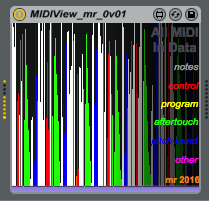
The second tool allows analysis of the values produced by the Controller simulator, and has lots of scrolling displays that provide plots of values over time. These are the same type of display as I used in the Mode Audio VeloView MIDI Velocity viewer that I've included on the right hand side of the screen-shot.
The main scrolling display allows the selection of the MIDI Continuous Controller Number, whilst there are separate scrolling displays for Data Entry (Controller Number 6) and Number 16. At the far right hand side, I have copied in the 32 buttons and the scaling and offset controls. Unlike the MIDIcc utility, this is much more a draft tool for my own use, and it isn't intended for casual users.
The Setup
Using the MIDIcc Continuous Controller simulator, the 32 buttons were easy to select with mouse movements, and substituting the Mod Wheel again produced jerkiness and difficulty in selecting a specific button. This meant that it wasn't my M4L processing that was causing the problem, but something else. Tracing back from the Plug-in, the MIDI signals went through Live, then through a USB cable to a MIDI Interface, and then to the synthesiser. The simulation worked okay, so Live was not the problem, which left the USB cable and the MIDI Interface... Changing the USB cable made no difference at all, and so that left: the MIDI Interface, or the synthesizer. Changing the synthesizer made very little difference, so it seems that the MIDI Interface is the major contributor.I'm going to split MIDI Interfaces into three types, and use these to avoid naming any brand names in what follows. The three types are:
1. Low-cost, simple, in-cable interfaces. These typically have a MIDI In and Out cable, a plastic 'blob' in the middle, and a USB cable.
2. Mid-range, robust, stand-alone interfaces. These typically have MIDI sockets for In and Out (sometimes a Thru as well), and a USB socket. Some USB audio interfaces also have this type of MIDI interface included as well.
3. High-end, professional, multi-MIDI-cable interfaces. These have 2, 4 or 8 MIDI I/O sockets, are often rack-mountable, are almost always rugged designs with metal enclosures, and often have time sync facilities.
Inside a MIDI Interface
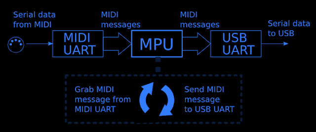
Inside a MIDI Interface, there are two sections: one grabs incoming MIDI messages from the MIDI In and sends them to the computer via USB; the other receives outgoing information via USB and sends them out via the MIDI Out. Here's the route from the MIDI In to USB:
The UART is a device that converts the serial data for the MIDI device into data in a format that the Main Processing Unit (or microprocessor) can work with by stripping off the start and stop bits and buffering the MIDI data. AT the output, another UART converts the MIDI data into the right format for USB. The MPU loops around, grabbing incoming MIDI messages, and sending them out to USB continually.
Interestingly, inside the microprocessor chip itself there are additional conversions going on:
Most modern microprocessors have serial interfaces externally, but internally, it is much faster to have data in parallel, and so there are more UARTs to convert to and from serial and parallel.
For MIDI Output, things just work in reverse in the other section. This time the MPU grabs outgoing USB data and converts it to MIDI data, with a UART formatting it correctly for MIDI transmission.
Inside a synthesiser
Just for reference, here's how the Mod Wheel typically works inside most synthesisers.
The left-most part is the Mod Wheel, which is just a modified rotary control where you move the edge of the knob, and this produces an output voltage. This is smoothed by the RC low-pass filter (just a resistor and a capacitor) and then converted into digital form by an Analogue-to-Digital Converter (ADC). Once in digital form, the processing is very similar to the MIDI interface: the MPU loops continuously, grabbing the Wheel position from the ADC, then converting it into a MIDI Control Change Message, and then outputting it to the MIDI Output with a UART.
Testing
I tried examples of each type of MIDI Interface to see if it made any difference to the controllability of he 32 buttons.Unexpectedly, the type of MIDI Interface made a huge difference!
At this point, I should explain how the scrolling displays in the analysis tool work. Each time a new MIDI Control Change value arrives, it moves the display to the left, and draws a vertical line representing the new value. The result is that the display scrolls leftwards as new values as received by the tool. This removes any dependence on timing, and gives a pure mapping between the incoming values and the display. Just as with the diagram at the start of this blog entry, the output should be linear for rising controller values, and linear for falling controller values. Any missing values will appear as a vertical jump, any repeated values will appear as horizontal flat segments, and any zero values will appear as gaps.
A perfect MIDI Interface would produce neat straight-sided triangles as the Mod Wheel is moved up and down (and the MIDIcc tool produces perfect triangles (as above), of course!)
Low cost, type 1 MIDI interfaces give different slopes each time, with missing values. The low cost probably means that a slow MPU with just enough processing power is used, and this is fine for most of the time, but runs into trouble when lots of messages are received all at once - as with sending lots of MIDI Control Change messages when using a Mod Wheel! (One other time that processing bandwidth is important is when using System Exclusive messages, and so they may also cause problems for this type of interface... I didn't test this.) The warped triangles explain why the Mod Wheel was so difficult to use to select buttons!
Mid-range, type 2, MIDI Interfaces give very good results, with only a few missing values. In this type of design, the internal microprocessor is probably better specified to cope with demanding situations, and the result is a pretty linear triangle.
High-end, type 3, MIDI Interfaces give good results, but not quite as good as the Mid-range, and this might reflect the higher processing demands of multiple MIDI sockets and time synchronisation.
Here's a summary of the three types:
For each type, the left hand column shows the biggest jumps between Control Change values (higher is worse), and then the right hand column shows how many different values were transmitted by the MIDI Interface. So the Low-cost type 1 only sent 25 messages with the largest gap of 13 when movie the Mod Wheel upwards, and only 32 messages when moving the Mod Wheel back to the resting position. In contrast, the Mid-range, type 2, MIDI Interface produced nearly three times as many messages (72) and had the smallest gaps (6).
The 'Min' and 'Max' values are interesting because they show the highest and lowest values sent in the Control Change messages. A Mod Wheel should produce a value of zero when it is in the resting position, but the low-cost interface only ever sent 3 as its smallest value. In my M4L application, this means that the first button could never be selected! (I cured this by adding an offset so that the Mod Wheel has 'dead'-zones as the two ends of its travel.


No comments:
Post a Comment