Yes, I'm late with my 'Waveform or Spectrum' blog post: part 4 of the 'Single Cycle' series. In the meantime, to illustrate the preparation that goes into my posts, here's how I made a custom 'Thru' box for my low-cost 'build it yourself' digital oscilloscope to make it easier to look at audio waveforms on quarter inch jack plugs. (or 3.5mm mono jacks for Eurorack...)
'Build It Yourself...'
You may have seen them on Smile.Amazon... - there are quite a few low-cost, single channel, digital oscilloscopes with enough bandwidth for audio but not much more. I bought a kit for a DSO 138mini produced by JYE Tech (www.jyetech.com) that came with a clear plastic case, built it and it has served me well whilst I dither trying to decide which real scope to buy! Maybe I should do a blog post on how doing research aimed at finding the 'right' product can slow down GAS (Gear Acquisition Syndrome) to a crawl...
Anyway, the kit comes with a 'probe' cable which has a BNC connector on one end, and two small crocodile clips with rubber covers on the other. The BNC connector is THE standard input connector for 'scopes', and I don't think I've ever seen any other connector used for this... However, those croc clips aren't very good with audio connectors. It is just about possible to grab hold of a 3.5 mm stereo jack...
...but the grip on a quarter inch jack is precarious, and feels like it is going to spring off at any moment.
What is needed is some sort of 'Thru' box - a way to connect to a quarter inch jack, whilst not interrupting the audio. So that's what I made...
Unlike previous 'mods' posts, this time I'm going to give a bit more detail about the construction. The circuit is simple: two jack sockets connected in parallel, and a BNC connected to the tip and sleeve.
You may have noticed that I have used stereo jack sockets. My thought was to make a mono and stereo jack compatible 'Thru' box, but when I started figuring out the circuit, I realised that there was a problem with having a mono and a stereo jack plugged into the box if I used stereo sockets, so I reverted back to using the jack sockets as if they were mono.
The Circuit
The circuit is very simple, the sleeve and tip of the two sockets are connected together, and also to the BNC socket that connects to the oscilloscope. On the sockets, these are the two outer connections, which makes it easy to solder.
When a mono jack plug is inserted into a stereo jack socket, then the tip, ring and sleeve make connections to the metal connectors. But because the ring connections are not connected to anything else, then they can be ignored.
I did contemplate going a bit 'British' with my design, by adding in a toggle switch to allow the selection of various different sockets to be connected to the BNC 'output' socket, but I eventually decided that the vast majority of sockets used in synthesizers and pedals (and my studio, which had a big influence) were quarter inch jacks.
For use with most modular synths, then there isn't a problem - Eurorack, Moog, Roland (and others) both use mono jack plugs and sockets (14 inch or 3.5mm - so just replace the 1/4 inch jacks with 3.5mm!), whilst Buchla (and my own first modular synth) use Banana plugs (or 4mm, as I knew them) and a Thru connection panel for 4mm plugs and sockets is trivial. And yes, I know that there are other connection systems used in modular synths: Wiard use Bantam plugs, ARP uses either 3.5mm mono jacks (2600, Odyssey, Avatar, Little Brother, etc.) or matrix slide switch panels (2500, etc.), and EMS use patch pins (which are actually tiny jack-like connectors - you can put resistors between the tip and sleeve!) for the Ghielmetti matrix patch panels, and there are others. I'm sure there are ways to connect an oscilloscope to these other modulars, but it is out of 'scope' for this blog post. (Did you see that pun?)
If you want to make a 3.5mm Jack version for use with Eurorack, then most of what follows is probably going to be useful, only the size of the sockets is different!
Drilling
Drilling holes for jack sockets is easy, but when they are going inside in a small cast metal box, then advance planning needs to be carried out to ensure that the jacks will actually fit, and so I pre-arranged the two jack sockets inside the (50x50x31mm) box and determined that they would fit, as well as the BNC socket. There are two sets of horizontal marks because I initially centred the sockets, and then realised that I also needed to leave room for the BNC socket, so I moved the two jack sockets lower to one side.
You can get a smaller box (52x38x31mm) than this one, and getting all three sockets into that would be more of a challenge - this would probably be worth looking into for a commercial design because the smaller sized box is cheaper. I have always had a soft spot for these die-cast metal boxes, and it is interesting to see that some guitar medals (at the 'boutique', end of the market in many cases) make a point of deliberately using that bare metal look.
Having decided that I could fit the two sockets inside the diecast box, I marked the positions for the holes and drilled small pilot holes first, then a larger hole, and finally the 10mm hole. I used a 10mm drill because it was the largest drill bit that I had immediately to hand, and so I needed to increase the size a little so that the 10.5mm diameter jack socket would fit. For this, I mis-used my trusty de-burring tool - going slightly beyond just taking the rough edges of the drilled holes quickly opened the holes up enough for the sockets to pass through.
I then used the box and holes as a jig to check that I would be able to solder the connections. It is always a good idea to pre-assemble things before committing to the final assembly.
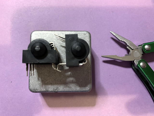
Here are the two sockets, using the drilled box as a jig, and you can see that it is easy to bend the legs (these are PCB-mount jack sockets, which I'm mis-using!). This version was my first attempt and so I bent all three pins of the stereo sockets. For the circuit as shown above, you only need to bend and solder the tip and sleeve.
When I marked up the holes inside the box before doing the drilling, I had noticed that space inside the box was quite cramped, and I worried that the other pins (the NC (normally closed) would short against the case. This shouldn't be a problem because the contacts open when you insert a jack, but this also seemed like a good point to mention heat-shrink insulation, which is the preferred way of insulating metal from touching other bits of metal, and preventing fingers and other objects from touching metal. The thin plastic adhesive tape that is known as 'insulation tape' or 'electrical tape is not really the ideal stuff for doing this, despite the name. The stickiness fades with time and the tape unravels. In more than 40 years working in electronics, I have never, ever seen insulation tape used to insulate anything!
In the above photo, you can see the un-shrunk heat shrink sleeving on the top right (just cut it to length) , the heat gun at the left hand side, and the sockets in the middle, with the NC pins shrouded in heat shrink. A more conventional use for heat shrink would be inside a jack socket, where you would use it to cover the solder connection to the tip terminal, so that if the braid shielding should come loose with use, it can't touch any of the metal associated with the tip, where the signal is...
I then used the box as a jig again, and soldered the pins of the jack sockets together. As I've already mentioned, you only need to solder the NO (Normally Open) tip and sleeve pins together. A perfectionist might put heat shrink sleeving on this pin...
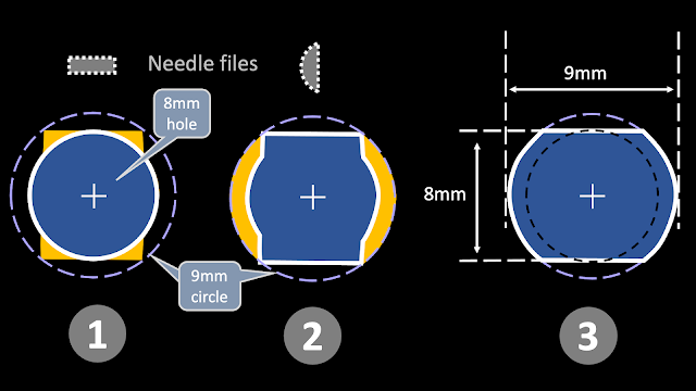
Next. the BNC socket. This is a little more complex, because the required hole is not round. BNC connectors work by your fingers twisting the plug onto the socket, so there's a lot of twisting force on the socket, and if it isn't securely held in place, then it will gradually loosen with time. Here's the hole that is needed for the BNC socket that I got, plus how I made it:
Stage 3 shows the final hole. It has two flat parts that would not be present if you just drilled a 9mm hole. So, starting at stage 1, I drilled a pilot hole, then a 5mm hole, then an 8mm hole. I then used a rectangular cross-section needle file to remove the metal shown in yellow - the top and bottom of this hole would be the flat parts of the final hole. Stage 2 used a half-round needle file to remove the metal in yellow - avoiding the two flat parts that were produced in stage 1.
This resulted in the final hole, as shown in stage 3 (and above!). When the BNC is mounted in this hole, the two flat parts of the hole prevent the BNC socket from twisting, and so ensure that it stays secure in the box.
Most PCB-mount sockets (like the jack sockets) don't have flat areas on the holes they require, because the PCB holds them in one orientation.
The strangely shaped pliers that I used to tighten up the jack sockets are called Wilkinson Quickgrips. They were originally produced for British Telecom engineers as an easy way to tighten nuts of a variety of sizes. These days they turn up at collector's fairs sometimes - I got this pair at a fair in Rufford in Lancashire.
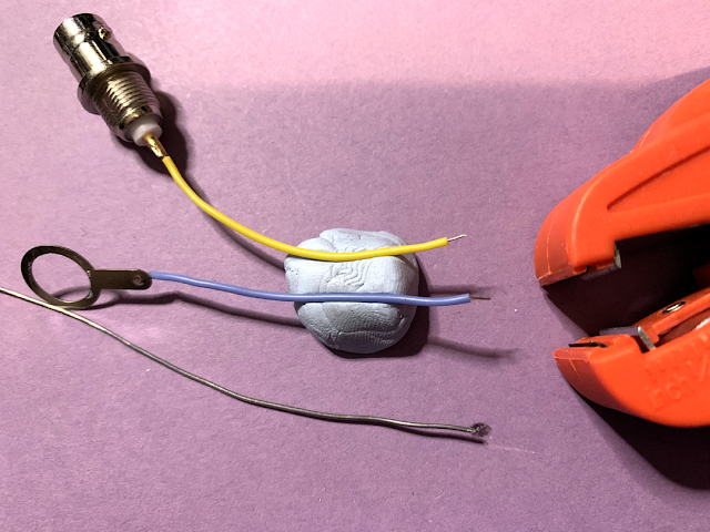
For the BNC socket, I soldered a wire to the centre terminal...
and another wire to the washer tag. I use Blu-Tack as a way of holding things down when I am soldering them. It helps prevent burnt fingers!
I then stripped the ends of the wires with a wire-stripper tool...twisted the wires...
...and 'tinned' the end of the wires by melting a little bit of solder onto them using a soldering iron. Tinning wires makes it easier to solder them to other bits of metal. In this case, I needed to connect these wires to the pair of jack sockets, so the tinning would make this easier.
Here's the inside of the box once all the soldering was done.
I then tested the thru box with my Studiospares UCT2 cable testing box to make sure that I didn't have any short-circuits, bad solder joints or other problems.
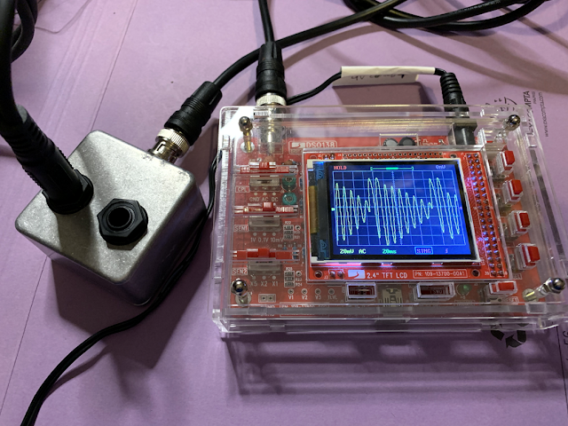
And here's the Thru Box connected to the BNC cable, ready for use.
And here the box is, being used to check a resonant single cycle waveform... In this case, I haven't used the 'thru' - I have just taken the output from a sample player and connected it to the Thru Box. If I wanted to hear it, then I would just use a jack cable to connect the other jack socket to an amplifier.
Links
---
If you find my writing helpful, informative or entertaining, then please consider visiting this link:
 Buy me a coffee (Encourage me to write more posts like this one!)
Synthesizerwriter's Store (New 'Modular thinking' designs now available!)


This comment has been removed by a blog administrator.
ReplyDelete