
The OWL pedal has stereo input and output jacks, as well as another quarter inch jack for an expression pedal, and this can be used to control many of the patches. There is also a small push-button on the top of the pedal that can be used to change patches, or as an extra input for things like tap tempo (particularly useful for sequencer patches, or for setting delay time). So far, pretty near a perfect solution for anyone who wants a programmable pedal.

But there was a minor niggle for me - that illuminated push-button on the top, right in the middle of the 'eyes' of the OWL - normally bright green, as shown in the photo above. Now it works very well, and is really useful for functions like tap tempo. In fact, it is so useful that I wanted to use it a lot and program it into my own patches (written in Gen, but that's another story). But it isn't really suited to live stage use because it is a small button on top of the pedal, and that would mean stooping down low and fiddling about down on the floor...
Actually, I can't complain, because the OWL pedal is published as Open Source Hardware under the GNU GPL, and the General Public Licence means that you are guaranteed to be able to share and modify the design, as long as you publish your modifications under the same licence. It's kind of the opposite of copyright, and so often gets called 'copyleft'. So if you go to the Rebel Technology web-site and so some searching, you will find the circuit diagrams, a bill of materials, PCB layouts and more - just about everything you might need to know about the design. So instead of complaining about the lack of a footswitch input, I added one!
Here's what I did.
The circuit diagram shows that the footswitch just pulls one of the micro controller input pins low when you press it, so all I needed to do was convert a footswitch so that it would do the same. Now there are two different types of footswitch commonly available: one type is a 'Normally Closed' switch, and is found in Roland footswitches, for example; the other type is a 'Normally Open' switch, and this is typically found in (for example) Yamaha footswitches. Now I happened to have a spare Normally Closed (NC) footswitch, so I built my circuit for this type.Just connecting my NC footswitch across the existing push-button wouldn't work, because that switch is Normally Open (NO). So I needed a simple invert circuit, and you can make this using a single transistor. Looking inside the OWL pedal, there's a space that looks like it was made for adding an extra jack socket, and there is room for a tiny circuit board as well, so a single transistor circuit sounded ideal. Hence the circuit looks like this:

The footswitch is that lonely switch on the left hand side, and it is open at the moment. The convention is that switches are almost always shown in the 'open' position, so you have to imagine that this is normally closed, and when you press down on the footswitch, then the switch will open. The input circuit has a capacitor to ground to slug any sharp edges, followed by a protection diode that stops negative voltages killing the transistor or the micro controller. And finally there is the transistor, which just acts as a switch. When the base (the input on the left) is at the right voltage then the transistor turns on and current flows through the 10K Ohm resistor, which pulls the PE2 output down towards ground. When the base voltage is below that voltage then the transistor turns off, no current flows, and the 10K Ohm resistor pulls the PE2 voltage back up towards the 3.3 volt positive rail. So when the transistor input is high then PE2 is low, and when the input is low, then PE2 is high. This means that we have a simple inverter circuit where the transistor is just behaving like a switch. Best of all, it now matches the operation of the push-button in the Owl pedal, and so all we need to do is build the circuit, add it to the existing hardware, and we are done!
So here's the gap and a spare jack socket:

Let's open up the OWL pedal:

And let's look more closely at that gap by the two input jack sockets...


We now need to drill a hole for the extra jack socket...

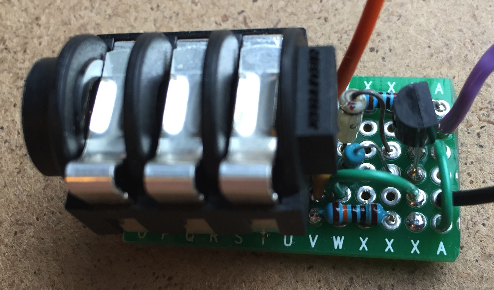
Then build the circuit on a piece of generic PCB mounted on the jack socket itself...
And then put it inside the pedal...

And connect the three output wires (shown on the right-hand side of the circuit diagram above) to the main digital board in the OWL (orange is 3.3 volts, black is ground, and purple is the PE2 connection):

Here's a diagram based on the Rebel Technology material:

And here's a view of the PCB with the pins marked again:

Finally, we put it all back together again:

...And there's now an extra socket, ready and waiting to be used for tap tempo and anything else that a patch programs it to do.
More information:
There's more background information, sketches, code and other material at my Github repository for this project.
WARNING:
As with any hardware project, you should only attempt this type of modification to an OWL pedal if you know what you are doing and are happy to carry out this sort of hardware hacking. I accept no responsibility for you messing up an OWL pedal. What you do with that pedal is up to you, and is your responsibility.


No comments:
Post a Comment