Tuesday 30 March 2021

MIDI Pitch Bend - A Tiny Inconsistency

Sometimes 'The Bears' really are lurking, ready to get you if you step on the cracks between the paving stones... 

One of the things that has been beaten into me, over many years of working with hardware, firmware and software, is a rule that has many forms, but which boils down to something like:

"Question everything. Measure everything at least twice. Always ask: 'Why?"

It is an expanded version of the 'Never Assume Anything' rule. It has served me well. But you must never let your guard down...

Ever...

Photo by Synthesizerwriter

The MIDI Pitch Bend Inconsistency

As with all unexpected things, it crept up on me silently, unannounced, from a direction I wasn't expecting. When you have spent a long time with something, then you think you know about it. Since I got my first copy of the original MIDI Specification back in the mid 1990s, then I have read it carefully and repeatedly. I spotted some of the things that were put in there by knowledgable hardware people who really knew their stuff, like what a MIDI Clock message actually looks like 'on the wire' of a 5-pin DIN cable, and why it was defined like that. And since you are now intrigued, I'm going to leave that until another post...

So the original MIDI Specification 1.0 (1996) has a section for Channel Voice MIDI Messages, starting with Note On (0x8n in modern formatting, but shown in mid 90's style as 8nH, where 'H' means Hexadecimal and 'n' is the MIDI channel (0x00-00xF or 00H-0FH for 1-16)), then Note Off (0x9n, 9nH), through to Pitch Bend (0xEn, EnH). After that you have the System Common MIDI Messages, which all start with '0xF'. So all of the 'highest bit set' values are specified, from 0x9 to 0xF.

The Pitch Bend message is the last of the Channel Voice messages to be specified, and the specification  contains just two paragraphs - the second of which is just two sentences and is just clarification about sensitivity. Here's that first paragraph:  

This function is a special purpose pitch change controller, and messages are always sent with 14 bit resolution (2 bytes). In contrast to other MIDI functions, which may send either the LSB or MSB, the Pitch Bender message is always transmitted with both data bytes. This takes into account human hearing which is particularly sensitive to pitch changes. The Pitch Bend Change message consists of 3 bytes when the leading status byte is also transmitted. The maximum negative swing is achieved with data byte values of 00, 00. The center (no effect) position is achieved with data byte values of 00, 64 (00H, 40H). The maximum positive swing is achieved with data byte values of 127, 127 (7FH, 7FH).

There are quite a few important take-aways in this paragraph. Firstly: Pitch Bend messages are ALWAYS 14 bit resolution. Now I've done quite a lot of Max and MaxForLive devices, and Max is a very useful general purpose tool for exploring MIDI... In Max, there are two basic objects that are used specifically for receiving Pitch Bend messages (there are other, more generic MIDI 'parsing' objects...): 'bendin' and 'xbendin'. 'bendin' is the 'basic' object, and it returns 7-bit values for pitch bend of 0-127 (a single MIDI data byte), whilst 'xbendin' is the 'extra precision' object, and it returns 14-bit values from 0-16,383 (two MIDI data bytes)). 

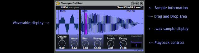
7-bit and 14-bit Pitch Bend objects in Max

The next important thing here is that the 'bendin' object is throwing away the second byte, the Least Significant Byte (LSB), so the values that you get are just the raw 7-bit values (0-127) that are in the Most Significant Byte (MSB). As I'm sure you know already, individual MIDI 'bytes' only have 7 bits available for data, which is why the value doesn't have the range of 0-255. You need multiple MIDI 'bytes' in a message to get extra resolution. In the 14-bit-oriented way that MIDI represents higher resolution numbers, then for a value represented with two 'bytes', the MSB is the top 7 bits, and the LSB is the bottom 7 bits. So the range covered by the LSB is from 0x0000 to 0x007F (0 to 127) in steps of 1, whilst the MSB is from 0x0000 to 0x3FFF, in steps of 128. Now 0x3FFF is 16,383, so that's where the full MIDI Pitch Bend resolution of 0-16,383 comes from.

Note. I need to point out that Pitch Bend messages, by design, should include 14-bit 'extra precision' values - as noted by the MIDI Specification - because pitch bend is a 'special purpose' controller. Max and MaxForLive provide access to the 7-bit lower resolution value only because that value can then be used for other things, anywhere in MIDI or Ableton Live, or even externally if you convert it to a Control Voltage. For the control of pitch, then 14-bits are a much better idea, because this will give you nice smooth changes of pitch.

Ok. All sorted.

Not quite. There's a problem. 

Pitch Bend is bipolar: it can be positive or negative. In MIDI, the 'no bend', middle, detented position is defined as being a value of 8,192 (0x4000 or 4000H), which would be output as a value of 64 from Max's 'bendin' object and as a value of 8,192 from Max's 'xbendin' object. Max does provide another special object, called 'xbendin2', and this outputs the two 7-bit Bytes separately, so you can see the actual MSB and LSB if you want to. 

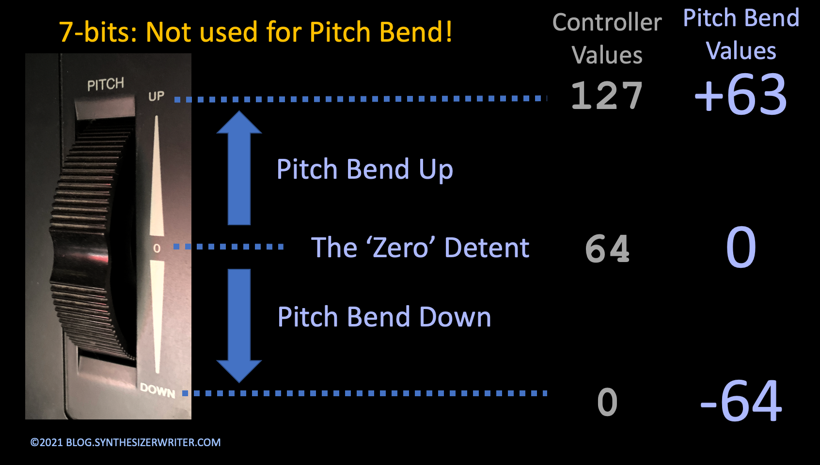
So negative Pitch Bend is the 64 values from 0 to 64 when we are talking 7-bit resolution, and the 8,192 values from 0 to 8,192 for 14-bit values. All perfectly fine and reasonable. But the positive Pitch Bend is slightly different. it can only go from 64 to 127, which is 63 values, because the highest 7-bit value MIDI allows is 127. yes there are 128 possible values in 7 bits, but if you start at 0, then you end up at 127. There are 128 values between 0 and 127. Max's 'bendin' object only provides 7-bit values for controlling other 7-bit parameters, and you would not use it for actually bending the pitch of a note - you would hear the steps! But the smaller numbers do make it very clear what is happening...

In 14-bits, then it goes from 8,192 to 16,383, and there are only 8,191 values, because 16,384 is ever so slightly larger than you can represent in a 14-bit number. 

The MIDI Specification 1.0 doesn't hide this. That final sentence of the first paragraph says:  

The maximum positive swing is achieved with data byte values of 127, 127 (7FH, 7FH).

The previous two sentences in the paragraph define the centre position and the maximum negative swing - but most people don't notice that 0->64->127 and 0->8,192->16,383 aren't symmetric. There is one less positive number than negative, and it is not hidden, it is in plain sight, printed in the specification. Unfortunately, the big numbers (16,383, and 8,191) tend to obscure what is actually happening...

In other words:

If no pitch bend at all has a value of zero, then the most negative pitch bend value is -8192. But the most positive pitch bend is 8191. (14-bit values are used here because these are what pitch bend applies to!)

Yep, The Bears just got us. 

The MIDI Pitch Bend Message doesn't allow us to bend up by the full amount. We can bend down and produce 64 7-bit messages or 8,192 14-bit messages (assuming our MIDI Controller outputs every value as a message, but that's another story). But when we bend up, then there are only 63 7-bit or 8,191 14-bit messages that can be output. That final value (8,192) is just outside of what MIDI allows. 

This means that if you set your PitchBend sensitivity to be 1 octave, then you can bend down by exactly one octave, but you will only be able to bend up by slightly less than one octave. The Owner's Manuals for MIDI Controllers, synthesizers and any other devices that output MIDI Pitch Bend messages generally say it exactly like it is - they say what the maximum positive output is. What they tend not to mention is that this is slightly less than what you need to do a pitch bend up that has the same range as a pitch bend down. And with 14-bits of pitch resolution, then the difference is very tiny. Miniscule.

In fact, I would guess that you've never noticed it...

So if you want exact pitch bend that utilises the end-stop of the Pitch Bend wheel or lever, then you should only bend downwards. This applies to any device that uses MIDI 1.0, regardless of age, firmware, operating system or manufacturer. Oh, and MIDI 2.0 is... different, because it has even higher resolution available.

Actually, there's another solution, and that is to not use the limits of the Pitch Bend wheel or lever (or push pad, or however it is implemented on your device), and that is to set the range to one note more than you require, and then to only move the wheel, lever, etc. by the amount required to get the bend you actually require. So for an octave, you might set the range to 13 notes up and down, and then only ever bend up or down by 12 notes. This gives perfect pitch bending, albeit with slightly less than the resolution of 16,384 values that were intended by the MIDI specifiers (but only very slightly less!). It does mean that you can't use the end stops of the wheel, lever, etc, but that's a minor inconvenience, and Pitch Bend by ear is so much better than relying on mechanics...

Oh, yes, and if you are thinking that this is a tiny difference in the pitch bend, and that it doesn't matter, then re-read that section in the MIDI Specification 1.0. It says that the MIDI Pitch Bend messages always use 14-bits resolution BECAUSE '...human hearing... is particularly sensitive to pitch changes.' I will gloss over the fact that it then goes on to define positive MIDI Pitch Bend so that it isn't perfect in precisely the place where human hearing is particularly sensitive. 

Not an Error

Actually, there is no error at all here. Nothing to see. This isn't a mistake by the people who wrote the MIDI Specification 1.0. It is nothing more than a consequence of the way that number work in these particular circumstances. Image the simplest pitch bend controller: three positions, No Pitch Bend (in the middle), Full negative (at one end of the travel of the wheel, lever...), and Full positive (at the other end of the travel). So these could be represented by -1, 0 , and +1. But this gives a jerky pitch change, of course!

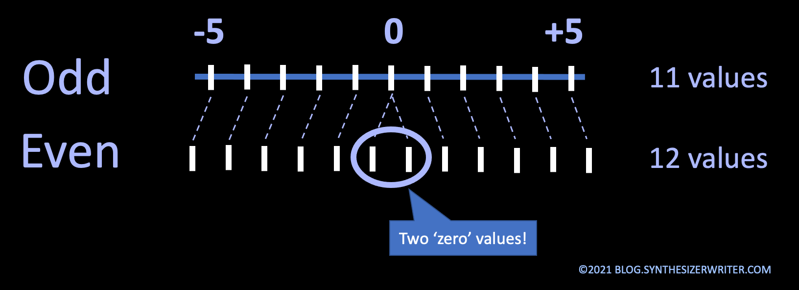
If we increase the resolution by 5 times, something interesting happens. The range is now -5 to 0 to +5, and there are 11 values instead of the 3 values that we had for -1, 0, and +1. So if we start with the most negative value (-5) and assign it to 0 on the pitch wheel, then the middle (zero) value will be at 6 on the pitch wheel, and the most positive value will be at 11. Aha!: We have a Marshall Amplifier 'goes up to 11' situation. Unfortunately, no matter how the range and the resolutions are set, there will always be an odd number of values, consisting of the negative numbers, plus the negative numbers, plus that zero in the middle. So we need a controller with an odd number of values (which would also be very useful for that Marshall amp!)...

The binary world of computer is even. The basic counting system (binary) is based on two values: 0 and 1. So if you have just one bit to represent a number then there are two possible values: 0 and 1. Two bits gives four values: 00, 01, 10, and 11, which are 0, 1, 2, 3, and 4 in decimal number form. Any number of bits used will always give an even number of possible values. MIDI's 7-bit numbers have 128 different values, which are normally shown from zero: 0 to 127.  MIDI's 14-bit numbers have 16,384 different values, and if we show them from zero they go from 0 to 16,383. 

(Decimal numbers are even as well! So are pairs, dozens...) 

When we take these even numbers of possible values and try to map them on to a Pitch Bend wheel, lever, etc. then there's a problem, because we now know that the total number of pitch bend values are always odd since there has to be a zero in the middle. The positive and negative values are symmetric and have the same range, but the need to have a zero position in the middle adds an extra number and we get an odd number of values. No matter how hard you try, if you have an even number of drawers and an odd number of things to put in those drawers, there will always be at least one empty drawer or thing left over (each drawer will hold only one thing, of course, in this scenario - which matches the way that numbers work very nicely!). 5 drawers and 4 things? One drawer will be empty. 4 drawers and 5 things? One thing will be left over, because all the drawers will be full. 

One possible solution is to have two zeroes! If you assign two of the values in the middle to zero, then you can have perfect matching! 

In the case of MIDI Pitch Bend, the design puts a single 'no pitch change' zero value at 8,192, full negative at 0, and full positive at 16,383. So the negative range has 8192 different values (0 to 8,192), and the positive range has 8,191 different values (8,192 to 16,383, which is 8,191). There is no value of 16,384 because that would require a 15-bit number, and we only have 14-bits. 


So the biggest negative pitch bend message value is -8,192, and the biggest positive pitch bend message is +8,191. The biggest possible positive pitch bend is always going to to be 1/8192th smaller than the biggest negative pitch bend message value. And it is a teeny, tiny value! Nothing to worry about. It is a minute pitch difference.

But it is an inconsistency!  


---


If you find my writing helpful, informative or entertaining, then please consider visiting this link:

Synthesizerwriter's Store (New 'Modular thinking' designs now available!)

Buy me a coffeeBuy me a coffee (Encourage me to write more posts like this one!)


Sunday 7 March 2021

Emulating Turning a Circuit On and Off...

On the Discord channel of the Music Hackspace, @MeLlamanHokage asked about simulating power failure in a circuit using Max. I replied:

For audio circuitry then you would need to implement things like: a low-pass filter with a falling cut-off frequency, an increasing noise floor, rising (or falling) gain, falling clipping levels (eventually to zero volts), rising intermodulation distortion, a changing dc offset...

(Here's a sneak peak of what was in my head - scroll down for more details):


And so I idly wondered if it would be possible to do this in Max - actually MaxForLive, because I realised that this might be a perfect addition to the Synthesizerwriter M4L Tape (etc.) Suite. In much the same way as you record release 'tails' or 'triggers' on a piano, so that you capture the sound made when a key is released and returns to its 'resting' position, then I realised that an M4L emulation of a circuit turning off (and on again) could be used to add in the sound of Guitar Effects Pedals being switched in and out of circuit, or having their power removed. 

This was hugely reinforced when Christian Henson @chensonmusic (of Pianobook and Spitfire Audio fame) did a performance using just a piano sample loop and his pedal board with 23-ish pedals in a recent YouTube video (there are three Moog pedals off to the right of the screenshot, btw):

https://www.youtube.com/watch?v=yF6VKqpC-nA

Imagine @chensonmusic Christian Henson's head and arm hovering over a massed array of guitar pedal goodness...
Christian Henson @chensonmusic 'plays' his pedal-board...

That's two nudges in the same direction, so I stopped dithering, and started coding...

Now I know that the Effect/Bypass switches in guitar effect pedals are designed to not introduce any glitches or noise into the audio stream, and I know that they don't turn the power on and off to the pedal (well, not usually)! But not all of them will function perfectly, and power supplies do fail! I have had several synths, groove boxes and drum machines that made interesting sounds as you turned them off, and I would venture that this may be an obscure and under-utilised area of sampling. See the 'Reminder...' section near the end of this blog post for more thoughts on this...

Are the sounds made by foot-switches on guitar pedals part of a performance? That's an interesting question... So how can I make it easier for everyone to explore this aspect as well?

Free Samples...

Whilst there may be little actual sonic effect on audio signals from a modern foot-switch, there's also the very characteristic sound that guitar pedal foot-switches make in the real world: definitely something to sample and use as a drum sound. (I notice that the BBC overdubbed the sound of a gun being cocked to replace the sound of a seat belt clicking in a recent 'edgy' trail...) So I did some sampling of switches from a variety of sources*, and this turned into an editing session, and you can get the results here for free:


These samples were created by me, and are released into the public domain with a CC0 licence. There are the sounds of foot-switches, and lots more. 'Footswitch14' and 'Footswitch Toggle 14' are what I think of as the classic guitar pedal foot-switch sound, but you may have your own preference...

As always, let me know if you want more of this type of content.

*Sources: Eventide H9 Dark, EHX Oceans 12, EHX SuperEgo+, Poly Digit, Donner DT-1, MIDI Fighter Twister, Rebel Technology OWL, and some other obscure stuff...

ON Off Emulation

But back to the main topic! I hasten to say that my original reply wasn't based on having already seen something that emulated a circuit being turned on and off. Instead it was me quickly thinking about what happens when you remove power from a circuit. So now that Christian Henson had inspired me to  actually design something, I jotted down some more concrete ideas about what 'turning something on and off' actually meant, as well as what sorts of things would happen to the circuits.

The first thing I thought about was a state diagram. At first sight, this is obvious. There are only two states: On and Off. Duh! (And there's the trap, sprung...)

But, with a little more analytical thinking, it is slightly more complex than this. There are actually four states: Off, Turning On, On, and Turning Off. The 'Turning On' and 'Turning Off' states normally happen so quickly that we don't notice them, but the longer they are, the more you notice them. One example where I've done this type of thing before was in a few MaxForLive devices that I programmed where the volume can be set to rise or fall slowly. The 'generic' version is called '3rd Hand' because it almost gives you a third (and very steady) hand to control rising or falling volume...

http://blog.synthesizerwriter.com/2018/07/slow-fades-in-live-performance.html - 3rd Hand

What was really interesting was that when I included an automatic volume control in a device: https://maxforlive.com/library/device/5258/instsineatmosphere then the only feedback comment that I received was that it didn't make any sound, which was exactly what happened with an earlier 'Generator' device where you had to click on a button to get a sound, so since then I have not included this feature in many devices. Please let me know if you would like it to be included!

But back to 'states'...

This '4 states' approach is very useful for live performance where you want something to evolve slowly: like an audio drone that gradually evolves over minutes, or tens of minutes, or longer. If you've ever gone to a 'Drone' performance by William Basinski (there are other audio drone specialists) then you will know the power of a slow rising, changing sound. I saw/heard him when he performed at Ableton Loop 2017...there's something about live performance!

In a drone performance, then there's a lot of slow evolution of sounds, timbres, volume... (the 'Turning On' and 'Turning Off' states) and very little time when the soundscape is static ('the 'On' or 'Off' states). To revisit the old saying about music typically being made up of 'sound and silence', then a better recipe might be that music is effective when it contains interesting/evolving/changing sounds seasoned with  sprinkles of silence.

In this case, the change was all about what happens when circuits get turned on or off. And so I jotted down as my first proper approximations:

- Mains breakthrough from PSU

- Clicks, Crackle and Crunches

- Noise (Rising then falling?)

- Clipping of audio

- Loss of high frequencies in audio

And then I programmed a custom 'synthesizer' in MaxForLive, that used a 4-state slow On and Off generator to drive 5 sections producing each of the 5 features that I had noted. I'm sure there are more things happening, but this was a first attempt, and I'd never seen anything like this before... Now when I say 'I programmed' then that can make it sound like something trivial and rapid, but that isn't quite how the process works... Anyway, some hours later...

OnOff Emulation mr 0v01


There are five processing sections, plus a sixth 'control etc.' section on the right hand side. The layout is much the same as the Ironic Distortion and the Ferrous Modulation M4L devices:

Ironic Distortion - blog post.                   Ironic Distortion - M4L.com

Ferrous Modulation - blog post.              Ferrous Modulation - M4L.com

Each section has a 'Mix' slider, which sets the level of the output of that section, with a big 'Mute' button.


But because this device is all about controlling the 'Turning On' and 'Turning Off' states, then there are extra controls in each section which are devoted to setting how time affects each section. The big grey bar is the current On/Off stare: 100 (all of the bar is grey) is On, whilst 0 (all of the bar is black) is Off. The movement of the bar (up or down) shows how things change during the 'Turning On' or 'Turning Off' states. To the right of the bar are four rotary controls, plus an 8-button switch selector.  The screenshot above is for the I (Impulse) section, and so each starts with that letter. So I-On is the time for the bar to move from Off to On (the 'Turning On' time), whilst I-Off is the time for the bar to move from On to Off (the 'Turning Off' time). 

The 8 position switch in the middle controls how the bar moves. L is for Linear, and so the bar just moves steadily from top to bottom (a straight line graph). S is for Sine, so the bar slows down as it gets to On. Z is Sine-squared, so the slow-down is sharper. P is for Power, so the bar slows down as it gets to Off. Q is for Power-squared, so the slow-down is more abrupt. B is for Bipolar, so the bar slows down as it gets to On and Off. D is for Bipolar-squared, so the slow-down is more abrupt. Finally, the light purple S that is linked to the two rotary controls on the right is for 'Smooth' (or Log) and this provides two additional controls that let you change the time of a logarithmic slow-down as the bar gets near to  the On or the Off. 


The best thing to do is to listen to the effect that the controls have! It is a bit like the Flutter waveforms in Ferrous Modulation: sine sounds boring, whilst the narrow spikes sound jerky... You may find that the Smooth setting gives good control, but remember that the S, Z, P and B positions don't have the slow-down at one extreme, and so have a very different effect. If you find yourself over-using the Smooth setting, then deliberately choose one of the more abrupt options. 

Separate controls are provided for each sections because the final sound works best when each of the sections has different timing! If you have the same timing for all of the sections than it will sound boring... One of the settings that I like is to have the Clip section happen last, so that you last thing you hear is the distorted audio...

The Sections

From the left hand side, the sections are in two parts. The first two sections process the incoming audio signal: 

Freq. 

This section just applies a low-pass filter to the audio input, and lowers the cut-off frequency as the bar moves from On to Off.  (Or raises it as the bar moves from Off to On). This emulates that way that some audio circuitry loses high frequencies as the power supply is reduced.

Clip.

This section has optional Compression and Filtering, but the main effect is to apply clipping to the audio input, where the clip limits reduce with the bar, so there is no Clipping when the device state is On, but more and more clipping as the state approaches Off. Note that the volume drops to zero when the state is Off... so you don't hear the effect of extreme clipping when the limits are zero! 

The next three sections are generators, and so do not process the incoming audio:

Noise

White noise filtered to give it various colours. The 'Gain' control and the mixer slider are effectively the same control...

Impulse

Crackles, pops, crunches, and other 'Impulse'-type sounds are generated in this section. Because the source is random noise, then these will not repeat - every time a new and different sound will be produced. 

Mains

This is slightly strange - it introduces the sound of mains hum, which is weird if the power supply has been removed. But, curiously, as with many sound effects, nonsensical often seems to work. It seems that having mains hum fade in and out implies something happening with the power - a bit like the way that sparks always seem to jump out of control panels on spaceships and submarines in the movies whenever there's an explosion or a collision. 

None of these sections is particularly complicated. Each does just one generation or processing function. Feel free to look into the code to see how each works - there's no magic used. 

The Big Button

One the far right hand side is the Control section. This has the big 'On/Off' button, text that shows the current state (1 of 4 possible states), and a generous set of memories for your own creations - just shift-click to store, click to recall. 

Reminder...

It is probably worth noting that although this might appear to be just a generator of On/Off sounds, it is also a processor - the Freq and Clip sections process audio, so if you don't input anything then they won't produce any output. The ideal setup is to have a sound that you want as the basis of the final result, and then use OnOff Emulation as a way of 'bracketing' it with an On and Off emulation.

This is slightly different to what the Release Trigger or Release Tail samples are doing in a piano sample - they deliberately do not include the piano note itself. (You press down on a key, and then release it, so you get the sound made by the key itself and the associated 'action' mechanics, but you don't do this with a string vibrating. ) OnOff Emulation processes any audio that is sent to it, and then layers the mains, impulse and noise sections on top of it. 

And this set me thinking... What about a release trigger/tail generator? I've never seen a dedicated one, because all of the release triggers/tails that I've ever used have been just samples that are part of the sample set of a sampled piano... The only exception that I can think of is for Harpsichord-type sounds on a DX7 (or other FM synths,  etc.), where the sound of the jack hitting the string when the note is released, is synthesized separately using an envelope where the attack and decay are short, the sustain level is zero, and the release rises to the final/initial level to give an envelope that only affects the release segment of the note. Oh, and acoustic guitar sounds, where string buzz is also synthesized this way... There's probably more now that I'm thinking about it this topic...

So a release trigger/tail generator would have different sections, and actually might have some aspects in common with a 'Riser' synthesizer, although they don't seem to be as 'in vogue' as they were a few years ago. I remember suggesting that a custom riser could be made by processing a 'reverb'ed section of a track in an Ableton Loop Studio Session back in 2015, and got a tumbleweed reaction from the room, and the 'Name' Producer then made one using filtered noise and everyone else nodded their heads. I have always swum against the tide, by the way...

I have added this task to my 'ever-expanding' (as Loopop says on YouTube) list of 'things to do'.  Don't hold your breath, though: it's a long list and I'm very busy. 

And Finally...

I haven't really seen a device like this before. Well, actually, that's not exactly right, because I have - this is just a synthesizer, but not your common variety. This is a purpose-built 'custom' synthesizer made to produce just one type of sound.  What I haven't seen before is a synthesizer that is dedicated to making the sound of a circuit being turned on or off. But now I have. And so do you, now! I think it shows the power of Max that you can use it to make arbitrary sounds and sounds that haven't been made before (or maybe sounds that I think might not have been made before...).

My grateful thanks to @MeLlamanHokage for the original question about turning circuits on and off, and to Christian Henson for using a pedal board as a performance instrument at exactly the right moment to get me to turn speculation into reality. Thank you, sirs!

---

Getting ONOff Emulation

You can get OnOff Emulation here:

    https://maxforlive.com/library/device/7074/onoff-emulation

And yes, I realise that it should be called AUDonOFFemulation if I was to use my own naming scheme, but that just reads crazy!

Here are the instructions for what to do with the .amxd file that you download from MaxforLive.com:

     https://synthesizerwriter.blogspot.co.uk/2017/12/where-do-i-put-downloaded-amxd.html

(In Live 10, you can also just double-click on the .amxd file, but this puts the device in the same folder as all of the factory devices...)

Oh, yes, and sometimes last-minute fixes do get added, which is why sometimes a blog post is behind the version number of MaxForLive.com...

And no, I haven't had a chance to test it in Live 11 yet... To much to do, so little time...

Modular Equivalents

In terms of basic modular equivalents, then implementing OnOff Emulation is a mixer plus a VCF plus a Clipper plus a noise source, an envelope follower and a State-Variable Filter, plus a trigger and 10 AR envelopes. Nothing is complex, but there's quite a lot of separate bits to deal with, which can be tricky on a modular... 

Overall, I reckon that OnOff Emulation would require an ME of about 20. Alternatively, you could just take any modular patch and see what happens when you power it down and up. (Caution: Turn your amplifier volume down, and use a limiter on the input. Increase the volume slowly and carefully - with caution. Not recommended with headphones! Do not turn modulars on and off repeatedly and quickly!) 

---

If you find my writing helpful, informative or entertaining, then please consider visiting this link:

Buy me a coffeeBuy me a coffee (Encourage me to write more posts like this one!)


Synthesizerwriter's Store
 (New 'Modular thinking' designs now available!)