A week after the Europe Max meetup, the Music Hackspace had its first 'USA-timing-friendly' online Max meetup via Zoom.us. This time there were three short presentations, but the 'CV/Modular' breakout room afterwards was particularly interesting. The first question that was posed was simple: how to interface Max to a modular synth to make drum sounds (I think - please let me know if my recollection is faulty), but the answers were not so short/simple and so I thought that it would be good to capture them here as a blog post. This is just part of the discussion that happened, so you should consider joining in next time...
Max Interfacing
Cycling '74's Max software can output audio, video, and MIDI, but outputting Control Voltages (CVs) and Gates/Triggers for controlling modular synths are less immediately obvious. There are some resources available on the Cycling '74 web-site, but they tend to only mention 'dc-coupled audio interfaces' or cover a specific device.
DC-coupled audio interfaces are special cases of the ordinary audio interfaces that are used to get audio in and out of a DAW. There are also specialist Modular MIDI-to-CV converters which are audio interfaces that are specifically designed to be dc-coupled and output CVs. Let's look at these two variants first:
1. Audio interfaces
Audio Interfaces are perhaps the obvious starting point, given that many people have them. They are a popular purchase for anyone who wants to make music using a computer - and if we wind time back by a couple (or triple) of decades, then the solution then was a 'sound card': a plug-in card (ISA-bus was one popular type) that provided better sound generation capabilities than the basic computer itself, as well as more 'music-making friendly' sockets than 3.5mm mono or stereo jacks. Sound input in those days was something that was very unusual in an off-the-shelf computer, and a sound card provided audio input capability - but the quality was not quite up to CD standards unless you spent a lot of money.
Nowadays technology has moved on a lot, and 'as good as or better than CD quality' audio interfaces are now typically external boxes that connect to USB, although curiously, the computer socket remains stubbornly and exactly the same 3.5 mm mono or stereo jack sockets rather than quarter inch jacks, RCA/Phono sockets or balanced XLRs. I have always thought that if a computer was really designed for music use then it would not have 3.5mm jack sockets for audio... There again, there's money to be made by selling audio interfaces, and there are lots of adverts reminding purchasers of DAWs, audio editors and other music software that one of the first follow-up purchases should be an audio interface.

An audio interface is just a converter from the digital numbers used to represent audio signals inside the computer, to the analogue audio signals that you find on quarter inch jacks or phono connectors when you hook a guitar or a synth to a pedal and then to an amplifier (or these days, more probably a software emulation of a vintage, distorting amplifier connected to an emulation of a vintage, slightly mis-used speaker cabinet, connected to a very clean amplifier). In other words, an audio interface contains an Analogue-to-Digital converter to input audio into the computer, and a Digital-to-Analogue converter to output audio from the computer.
Audio interfaces normally get selected based on the number of inputs and outputs, the quality of the audio that they give, the highest sample rate (192 kHz for example), the number of bits that are used in the Digital-to-Analogue Converters (DACs) and Analogue-to-Digital Converters (ADCs) -16 bits is meh (CDs), 24 bits is high, and if they can run VST plug-ins (which also equates to expense). You might have noticed that 'Outputting control voltages for modular synths' wasn't in that specification list...

To output Control Voltages, you need an audio interface that has an unusual property in most audio systems. Audio signals are often quoted as being from 20Hz to about 20 kHz in frequency, from a low-pitched rumble to high pitched (kids can hear it but their parents can't) shrieks. The diagram above is impossibly perfect, but shows what an idealised frequency response might look like. As you go below 20Hz you feel wobbles rather than hear the audio, and eventually, at zero frequency, you get what is called direct current (DC) because it doesn't change (instead of current that changes all the time, which is called alternating current (AC)), which is where the wobbles stop and you just get a voltage (and a current flowing - there are various formulas that connect all of these things...). If you want a long explanation, just ask an electronics engineer why DC isn't called 'Direct Voltage'...
The problem with frequencies below 20Hz is that they are just wobbles, and you feel them rather than hear them. And getting a speaker to wobble can do nasty things to it - overheating, tearing itself apart, ripping the cone, warping in shape, etc. One way of experiencing DC is that thump you get when you power up amplifiers with the volume up high instead of at zero. So, to protect speakers (and people from being wobbled excessively), many audio systems don't go 'down to DC' (zero Hz) - they stop at about 20Hz.
Unfortunately, frequencies below 20Hz, and especially zero Hz (which is stopped = a fixed voltage!) are exactly what is needed for CVs. Control voltages like Pitch or Modulation tend to change quite slowly (60 bpm = 1 Hz (!) which is one complete wobble per second). and so will not be output by an audio interface that has no response below 20 Hz.
So what you need for CVs is an audio interface that has a frequency response that goes all the way down to DC (Zero Hz!), which is often called DC-coupled (because electronics engineers have jargon just like any other profession). The dashed line in the frequency response diagram above shows a response that goes all the way down to DC, but the log scale makes it difficult to show... Here's an example list from 2019 that shows some 'dc-coupled' possibilities then (you will need to research current devices...):
https://www.sweetwater.com/sweetcare/articles/which-audio-interfaces-are-dc-coupled/
If you look at the text in the Ableton Live 'CV Tools' device free download, then it says that you need to use a dc-coupled audio interface, but doesn't go into any more detail:
https://www.ableton.com/en/packs/cv-tools/
(Technically, it should be 'DC-coupled', but lower case is often used instead...)
If you want to check an audio interface, then looking for the phrase '20Hz-20kHz' in the specification is usually a good indicator that an audio interface is NOT DC-coupled. That low number: '20Hz', is the clue. My Focusrite Scarlett has exactly this phrase in its specification, and yep, it is not DC-coupled, and so isn't good for outputting control voltages. There again, the specs make it very clear, and I bought an 'Audio Interface', not a 'Control Voltage Interface'.
Sometimes the specifications can be difficult to interpret. Here are the specifications for the Native Instruments Komplete AUDIO 6 audio interface:
As you can see, the phrase 'DC coupled' is there! But only in the output (and also notice that it doesn't say '0Hz-20kHz! That would be far too obvious...). There again, the input doesn't mention the all-important phrase at all. There's a rule here:
If it is not in the spec, then there's probably a good reason why not...
This means that the output is DC-coupled, so you can use this audio interface to send CVs to your modular synth (or any synth with CV inputs), but that the input is NOT DC-coupled, which means that you can't use this audio interface to receive incoming CVs from a modular synth, a CV controller, or an analogue synth that outputs CVs. However, the inputs can have 48V applied to them, which is not recommended for connecting to most modular systems.
The specification has one additional, easily-overlooked 'feature'... There is an asterisk (*) after the 'for modular control... If you go to the end of the specification it says: *Limited to +/-2V range due to the AUDIO 6 being USB powered.' Aha! So the range of voltages that can be output is limited - which gives us another rule:
Always check for asterisks - they often try to hide a catch...
Something to be very aware of when looking for a DC-coupled audio interface is the actual output voltage range - and be careful to never assume anything. Even if an audio interface is DC-coupled, it doesn't necessarily mean that the range of voltages that it can output are appropriate. Let's look at a popular modular standard and see if that tiny little asterisk has any significance...
I'm going to concentrate on Eurorack modulars here, but there are other standards... Eurorack audio signals can be a maximum of 10V from peak-to-peak, which is -5V to +5V (+/- is known as bipolar). Eurorack control voltages can be half that size (-2.5V to +2.5V), but can also be what is called 'Unipolar' and range from 0V to 8V. Control voltages that are used for pitch usually follow a 1V/Octave rule, although there are other ways of representing pitch, particularly on modular synths from the 'Sound Card Era' and even before that! Gate and trigger signals are usually 0V for Off, and 5V for On. All of these numbers mean that you may need to amplify the output of a DC-couple audio interface in order to get the right voltage levels... so that Utility module may be useful after all!

In the case of the Native Instruments Komplete AUDIO 6 (Why is it shouting 'Audio'?) then the control voltages are slightly smaller than the Eurorack range in bipolar mode, but way too small for unipolar mode. This could limit the range of, for example, a pitch CV, which might not be what you want. Worse, if you aren't aware of the limits of the output voltage, then you might spend time trouble-shooting a problem that seems to be in the modular when it is actually in the audio interface.
Using audio signals to carry numbers is not new. Before broadband, modems used to turn the number in computer communications into frequencies so that they could be sent over telephone connections - and telephones are not DC-coupled! (300Hz-3.4 kHz for UK telephones). Data was (and still is) sent over radio by jumping between frequencies`; early methods used pairs of frequencies, whilst modern systems use more complex 'constellations' of frequency, amplitude and phase.
One other important thing to remember is that price and external appearance aren't going to give you a reliable indication of an audio interface being DC-coupled. Check those specifications...
In summary, then, audio interfaces come in two flavours: DC-coupled (which CAN be used to output CVs - but check the range), and Not-DC-coupled (which can't be used to output CVs). It is a good idea to stick a label onto your audio interface to indicate if it is DC-coupled (input, output or both, plus the range of voltages) or if it is not.
2. Modular MIDI-to-CV converters
A modular MIDI-to-CV interface is a purpose-designed converter that plugs into a USB socket and outputs Control Voltages (and sometimes inputs CVs and converts them to MIDI, although technically that would be a CV-to-MIDI converter!). So they go from DC up to the low wobbles (and maybe up above that where you can actually hear the frequency), and no need to amplify the output, the CVs are modular-compatible by default. Take care: a MIDI-to-CV interface module for one modular standard might not be suitable for another, plus the power supply might be different, and the mechanics will be different... As before, in this post I will only cover Eurorack...
One often-mentioned modular MIDI-to-CV interface is the Expert Sleepers ES-8, which has 4 analogue inputs and 8 analogue outputs on the front panel, plus various expansion options for additional I/O.
https://www.expert-sleepers.co.uk/es8.html. - Expert Sleepers ES-8
https://www.expert-sleepers.co.uk/es8usermanual.html - ES-8 Manual
There are other devices, of course!
https://mutable-instruments.net/modules/yarns/ - Mutable Instruments' Yarns
http://www.doepfer.de/a1903.html - Doepfer A-190-3 USB to CV/Gate
and plenty more...
Note that some MIDI-to-CV modules have 5-pin DIN inputs rather than USB sockets, so make sure to read the specs, otherwise you may need a USB MIDI Interface (most audio interfaces also provide MIDI I/O...).
The Arturia KeyStep
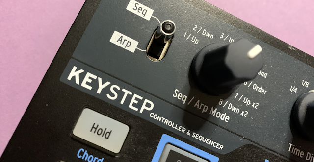
And then someone suggested the Arturia KeyStep. It has Pitch CV, Mod CV and Gate outputs, as well as MIDI In and Out.
The manual says that incoming MIDI notes are used as transpositions for the sequence, and are also converted to Pitch CV. So I looked for the MIDI Implementation Chart to see more information. Except I couldn't find one. Not in the manual. Not on the web-site. Not from a Google search. So I compiled one by testing exactly what the KeyStep actually does. You can download it from here...
Here's a summary of what I discovered:
- The KeyStep outputs Pitch CV based on incoming MIDI notes, plus whatever note is played on the KeyStep's keyboard, plus any Pitch Bend from the KeyStep's Pitchbend strip controller. Incoming MIDI Pitch bend messages seemed to be ignored (but this could be my error - please let me know if there is a way to make it happen...). Even so, being able to convert MIDI notes to Pitch CV was very useful - and lots of people have a KeyStep. Being able to add Pitch Bend to incoming MIDI notes can add a lot to a plain 8 or 16 step sequence...
- The KeyStep outputs Mod CV based on the Mod source that has selected in the MIDI Control Centre software from Arturia that is used to control the setup of the KeyStep (plus save sequences, etc...). Available source are the Mod Wheel, Velocity and Aftertouch. So if the Mod Wheel is chosen, then incoming MIDI Modulation (Wheel) Controller messages (CC1), plus the KeyStep's Mod Strip are added together and output as the Mod CV. If Velocity is chosen then the Velocity of incoming MIDI notes is added to the velocity of notes played on the KeyStep's mini-keyboard and output as the Mod CV. And finally, if Aftertouch is chosen as the source, then incoming MIDI Aftertouch message values values are added to the Aftertouch values from the KeyStep's mini-keyboard and output as the Mod CV (cool for a modular where people don't normally them to respond to Aftertouch). Lots of scope here for double keyboard possibilities, particularly adding Aftertouch to fast lead lines on a keyboard - where you don't have enough time to press on the keys to activate the Aftertouch.
- The KeyStep outputs Gates only when its mini-keyboard or internal sequencer/arpeggio outputs a note. I couldn't get it to respond to incoming MIDI notes. Now there is lots of scope for experimental error here - the MIDI Control Centre provides lots of control over how the KeyStep behaves (like choosing the source for the Mod CV - if you choose Velocity or Aftertouch, then it might appear that incoming MIDI Mod wheel messages are ignored...), and I might have missed a vital setting. So I'm happy for all of this to be a draft, and if anyone has any additional information about how the KeyStep responds to incoming MIDI messages, then please let me know and I can update the MIDI Implementation Chart (and this post).
As a workaround for the lack of a Gate output, you could use Mod Wheel, Velocity or Aftertouch Mod CVs through a Utility module and create Gates using a threshold function. You could even use the value as a CV as well. You could also buy a MIDI-to-Gate/Trigger module! (GAS can be very bad with modular synths...)
The KeyStep is thus a partial solution to converting MIDI to CV so tat Max can be used to control a modular synth, and it opens up some creative control possibilities that aren't normally very easy to do.
This is probably a good time to think about how closely related audio signals, controls voltages, and gates/triggers are in a modular synth. An audio signal can be used as a fast LFO, whilst a fast LFO can be an audio signal. A pulse LFO can be used as a continuous series of gates or triggers, and so on. A MIDI-to-CV module emphasises the interchangeability by making numbers in Max appear as voltages in the modular synth - so numbers that go up and down from a cycle~ object could be an LFO or an audio signal, whilst a number that stays the same for most of the time, but occasionally jumps up to a higher value, and then jumps back to the original value again, could be used as a gate.
What a voltage does is defined largely inside Max by how the numbers change, rather than by the modular synth - the modular bit is just the way of turning those numbers into sound. This is why modulars are more interesting than conventional fixed architecture synthesizers...
But a lot of the fun of electronic music is DIY, and so here's some information on other ways that you can interface Max to a modular synth or an analogue synth:
3. Other possibilities...
In electronics, there are often alternatives. If you have any electronic design experience, then a frequency-to-voltage converter could be an interesting way to explore using an ordinary audio interface and Max's audio generation capability to convert frequency to voltage.
Frequency-to-voltage converters often use a pulse generator plus some sort of averaging circuit (a low pass filter, for example) - so for the averaging circuit you could have a leaky 'bucket' (which could be a capacitor with a resistor that causes the voltage to 'leak' away), and a pulse generator circuit could be just a way to fill the 'bucket' with cups of water. The faster you put cups of water (pulses) into the bucket, the higher the voltage level, and so the frequency determines the output voltage.
There are chips deigned to do frequency-to-voltage conversion, and all you would need to add is an input buffer and an output scaling amplifier (probably just an op-amp).
Here's some information about a few methods of converting F-to-V, mostly using dedicated chip-based Frequency-to-Voltage convertera:
If you want to have something curious to think about, consider this: a Frequency-to-Voltage converter is just a reverse VCO. (A VCO turns a voltage into frequency...)
Because it comes from a legendary analogue circuit designer (Bob Pease), I'm inclined to forgive the blatant and incessant advertising on the following web-page (if I ever needed a reason to use an ad-blocker...):
You could use a Utility or Trigger module to threshold the output voltage and produce Gate or Trigger voltages, where low frequencies produce a low voltage output (Off) and higher frequencies produce a higher voltage output (On). Again the input will need to be buffered and scaled, and maybe offset. The core part of this, a F-to-V device converting 0-10kHz to 0-10V, is available as a £6 circuit board from Smile.Amazon.co.uk... Given the price of many modules, then this is a (unipolar mode) bargain! Steampunk experimentation awaits for brave synthesists!
The problem with using a chip or circuit board as a 'black box' is that you don't get any real feel for what is happening, so here's a circuit that does what the cups and bucket does:
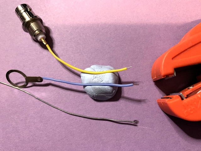
...and here's how you could use the same circuit in a modular synth to make a simple Frequency-to-Voltage converter - you just solder a few components onto two 3.5mm sockets (or you could just cut a 3.5mm cable into two...
For experimentation purposes then '
rats-nest' style is fine by me, although you could use a prototyping bread-board if you wish. I'm always intrigued by modular owners who have modules for everything, but who never actually do any DIY circuits. A modular is a DIY synthesizer, so why not build your own circuits to process audio or CVs...
Using frequency-to-voltage converters may have other side effects: the latency might not be very low, but this might contribute to the appeal. For example, Buchla-style Low-Pass Gates have interesting time response characteristics which create a lot of their special sound. Modulars are very good at exploring these types of circuits - you could almost think of them as laboratory toolkits for audio electronics...
Frequency to voltage conversion is an old technique, hence the steampunk reference above. one of the first circuits that I ever had published was a variant of the diode pump, used to indicate if a clock was running or not... Frequency-to-voltage converters turn up in all sorts of equipment: radios, tachometers, speed controllers, and more...
Open. not closed...
Hopefully this post will help Max (and MaxForLive, PureData, and other similar programming environments...) users to control some of the real world beyond their screen.
Interfacing Max to other devices, sources of numbers, other controllers, synthesizers, modulars and more opens up huge possibilities. One of the dangers of creating music on a screen is that the screen can become the only focus of the environment, and there is a strong temptation to put everything on the screen because of the immediacy, ease of editing, convenience... I believe that the most interesting challenges and opportunities in making electronic music come from the interfaces between the real and the virtual, the human being and the synthesis equipment, the possible and the 'to be solved', the screen and beyond, because that is where magic happens.
---
If you find my writing helpful, informative or entertaining, then please consider visiting this link:
Synthesizerwriter's Store (New 'Modular thinking' designs now available!)
 Buy me a coffee (Encourage me to write more posts like this one!)


