Okay, so I have known about Gen for a long time (since it was called gen~, in fact), and I have always kind of overlooked it. I'm sure I'm not the only person who glances at it and thinks that learning to program in it is going to require time to learn it, and given the plethora of programming languages that I already know, acquiring yet another one is revisiting that 'start at the bottom yet again and claw your way up to the point when you can actually program things that almost do some of what you intended' learning curve that I have climbed many times before.
Just as in writing a novel, learning Gen requires something that breaks the hero/heroine of the story out of their normal humdrum ordered world, and forces them to go out and have an interesting adventure instead. In my case, the trigger was a casual conversation with a name producer, who said that what they really wanted was something that would let them do [possible subject of a future blog posting]
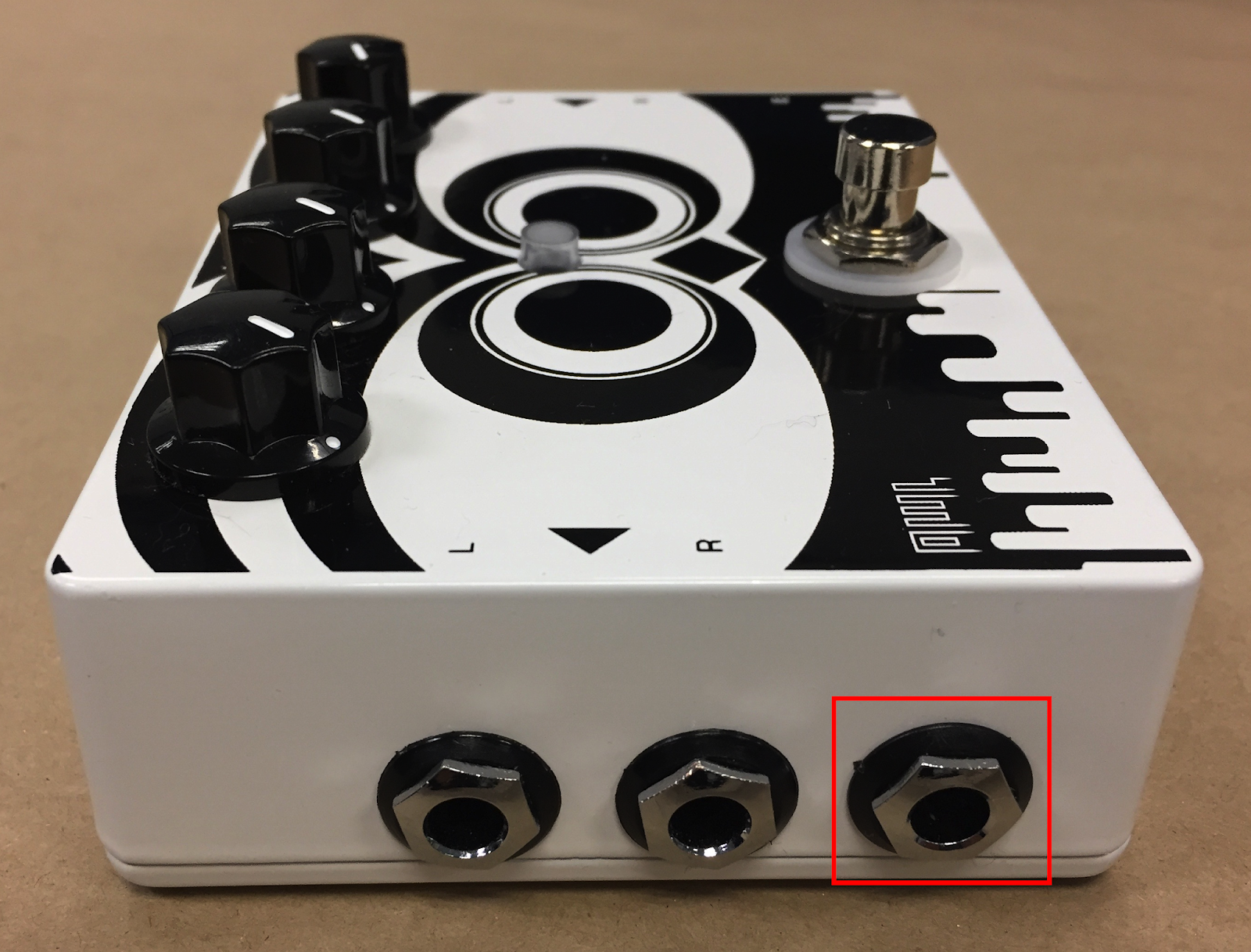
At the back of my mind, driving my confident assertion: 'there are ways', were the various hardware platforms that let you program them, not in Max, but in Gen. Things like the MOD Duo, or the Rebel Technology OWL Pedal. After comparing the specifications and the prices, I went for the OWL Pedal as my first test development platform, leaving the MOD Duo as a potential future addition to my portfolio.
Rebel Technology OWL Pedal
Rebel Technology describe themselves as a London based tech collective creating radically innovative music electronics since 2009', so they immediately sounded interesting - and they were at the 2017 SynthFest UK in Sheffield too! Alongside a variety of Eurorack modular stuff, they also do a completely programmable microcontroller-based development platform called OWL, that is available as a pedal or as a rack module (and more variations coming up soon). I went for the OWL pedal, and after the usual 'wait for the postman' delay, I soon had one. Having a piece of hardware kind of ups the commitment level, so I read all the documentation, watched their YouTube videos, and generally immersed myself in Gen. [Montage of time passing whilst being immersed in Gen...] 
What I discovered was interesting, and there was an annoying little 'told you so!' voice at the back of my mind that kept reminding me what Cycling '74 have always said about Gen: that it isn't as scary as people think, and that it enables you to do amazing things, but that the one enabling thing you need to learn is a different way of looking at programming. In the case of Gen, that 'different way' is having to think about doing everything at the sampling rate, and that's quite a fundamental change in the way you conceptualise things. It's a bit like learning to hand-craft web-pages using only HTML, and then discovering that you've done it all wrong because you should have been using CSS for the layout, and HTML for the content.
My learning style hasn't changed much over the years. From the Intel 8080 onwards, my first program has always been a 'Hello World!' type of simple test, and then I have iteratively added bells and whistles (sometimes literally) until I eventually get to that 'do some of what you wanted' point. This method works for the small projects that I tend to work on, but there are lots of other ways of learning and programming that may suit you better. Whatever works for you.
So as my first patch, I wrote a patch for the OWL pedal (and it should work on the modular rack module too) that used an Expression pedal connected to the OWL Pedal to control the volume of an audio signal passing through the OWL pedal. Yep, 'Hello World!' for audio on the OWL pedal. Here's the basic patch, written in Gen:

Now it isn't immediately apparent when you first look at the patch, but there's something really interesting happening here: all of this is audio signals sampled at 48 kHz. So there are two audio inputs (in 1 and in 2 for the left and right input channels of the pedal), and these are connected to two multiply boxes (which contain just '*') and the output of the multiply boxes are connected to the two audio outputs (out 1 and out 2 for the left and right output channels of the pedal). So for every sample (48 thousand times per second), the in 1 audio input sample value is multiplied by the multiply box and the output goes to the out 1 audio output. If you multiply something by zero then you get nothing out, and if you multiply something by one then you just get the original value out. The source of this 'multiply' value is the Expression pedal (Exp). So this means that 48 thousand times a second, the position of the Expression pedal is sampled, and that sample value (between 0 and 1) is used to multiply the audio sample value from in 1 and in 2, an the outputs get sent to out 1 and out 2. That's 96 thousand multiplies happening per second inside the Owl pedal so that the volume of the inputs can be changed by the Expression pedal. Also, it means that if the Expression pedal potentiometer is even slightly imperfect, then we aren't going to get a smooth volume change, because the Expression pedal is sampled for each and every sample! Any noise or bad connection in the potentiometer is going to give the wrong value for the multiply value, and the output will jump up and down in volume. This patch design has lots of scope for improvement!
I followed this with a second patch that used the Expression pedal to pan the audio signal from left to right, and which used one of the OWL pedal's four control knobs to set the 'pan' law so that you had some control over how abruptly or smoothly the panning happened. Here's the basic patch:

This patch sorts out some of the problems in the first patch by adding a few extra boxes - compare the two patches first so that you can see what the changes are... The Expression pedal is now passed through a 'slide' box. This smooths the value so that any sudden jumps don't appear at the output. The final outputs from the multiply boxes are now limited to +1/-1, so if the multiply value somehow gets bigger than 1, then we aren't going to get excessively loud outputs - just distortion limited to +1/-1. The previous patch treated the two channels the same, but here we want to pan from one channel to the other, and so the smoothed Expression pedal sample is inverted for the in 1/out 1 (left) channel using the box with '!- 1.' in it. What this box does is subtract the Expression pedal value from 1, so a value of 0 outputs a 1, and a value of 1 outputs a 0. (This is just a weirdness of the way that Max does this type of function - just think of it as 'inverting' the value) So as the Expression pedal goes from 0 to 1, then the two channels will get opposite multiply values.
Unfortunately, pan isn't quite as straightforward as this in practice. So here's a revised version that sounds much better - and notice the extra multiply boxes, two new boxes and a new control...

What those boxes do is change the 'pan' law - the amount of overlap as the audio is panned across the stereo image. What happens is that the smoothed D' control knob on the OWL pedal is used to control if the law is linear or uses a quarter sine wave 'non-linear' law. (this is what the 'expo' box is doing). This isn't a perfect way of doing this, and there are much better ways of doing it, but it is simple and works quite well for my ears.
(Don't worry about going back and re-reading this explanation as you trace through the patch diagram - there's a lot happening here, and as I have said too many times already, it all happens 48 thousand times per second!)
Having said that Gen is a 'deeper level' than Max, then it is probably time to show how Gen fits into the Max programming environment. Here's the Max patch that the Gen code is 'inside':

As you can see, the Gen code looks just like any other Max object, and the programming environment is familiar. It's just that things work a little bit different inside the 'gen' object... At the level of the Max patch, then we set up the inputs and outputs, and you can see that I have left a couple of number boxes and 'scope' objects in the patch, ready for using to view what is happening inside the Gen object -
which is the little box on the mid left hand side that I have put a purple rectangle around.

Gen doesn't provide the same depth of assistance as Max does, and so you need to do a bit more work to monitor what is happening inside a Gen object by using extra in or out objects. I think of it as a bit like trying to do things through the letterbox in a front door... I will try to show how this works as we go along, because it is one of the key skills to have when developing Gen, and it is easy to overlook when concentrating on the Gen code itself...
(It is also important to point out here that the OWL Pedal is only going to do the stuff inside that 'gen~' box. Some of the standard Max functionality isn't implemented in Gen for a variety of reasons, and so you need to approach things slightly differently - so it isn't just a case of putting standard Max objects inside that gen~ box, and you can't add Max objects outside of the gen~ box and expect them to work. 'Inside the gen~ box' is the key to this.)
My next patch took one of my old MaxForLive patches, and turned it into Gen. I had to do quite a bit of user interface simplification in order to cope with only having four control knobs, an Expression pedal and a pushbutton, but the result was quite encouraging: a stereo delay box with an unconventional way of doing things, and some quite unusual sounds. Rather than bore you here with yet another 'unique' delay patch (for some reason, the world is full of delay patches whose creators think are amazingly different), then it felt like time for some more novel writing 'advance the plot' activity. If you are interested, then you can find the patch in the online library for the OWL devices - I'm called 'registration' because that's the email account name that I used. I'm also going to upload it to my Github repository at some stage...
Anyway, having told you about all of this preparatory work, it was now time for the next step nearer to what I had been so confident I could make for that producer. I took an idea and turned it into a patch, without basing it on a tutorial. This patch is the real topic of this blog post!
Four Step Sequencer
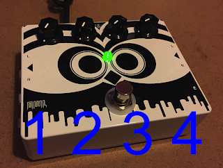
The OWL pedal has four control knobs, so it makes a four-step sequencer an obvious choice, and I wanted to make something self-contained: a step sequencer plus a simple sound generator. Using the pushbutton as a tap tempo source leaves just the Expression pedal as a possible timbal control. So if you have only one control, what gives the widest range of sounds?After a bit of experimentation... Okay, after a lot of messing about... I dragged myself away from my modulars and decided on a slightly unconventional approach influence by Reaktor-style sound generators (Look up 'Flintpope' for some amazing examples!). I would use that single remaining control to set the rate of an LFO that sweeps a resonant low-pass filter past a pair of detuned oscillators, which is quite a lot of indirection... This means that this patch is more self-contained, and a bit more like a factory demo than a generically useful patch (and I've done various bits of paid 'impressive demo'-oriented work over the years), but as a learning patch, as something for people to tweak, to derive other patches from, then I think there is huge value in demo patches, especially when they aren't buried in reverb.
So how do you do timing in a the world of Gen? If everything is happening 48 thousand times per second, how do you work at a slower rate? The solution I chose is to just use a counter so that we slow down those thousands of times per second into something that works at a more human-oriented rate. You can do this in gen~ by using the 'phasor' object, which is a counter that counts from 0 to 1 at a rate set by a clock rate derived from the processors chip's master clock. There are lots of other ways to do timing in Gen - using the 'phasor' object is just how I did it in this case. Let's start by looking at the whole finished patch:

Okay, so there's lots more happening in this patch! So let's break it down into sections and look at each of those in isolation.

Top right deals with the timing, and that's where we will start. Across on the top left is the sequencer, and the lower half is the audio section.
Let's start with the timing. There are two linked timings that we need: one to produce the 4 steps that we will use for the sequencer timing, and another one to produce the envelope timing for the notes played by the sequencer. The sequencer timing is the easier of these to understand, so let's start with that.
Step sequencer


The output of the push-button goes into a pre-prepared 'encapsulated' gen~ object (from a Rebel Technology tutorial example) that measures how many 48 kHz clocks happen between presses of the push-button ('taps' in tap-tempo-speak) - a 'tap-tempo' box. The 48 kHz clock is the master timing source in the microprocessor used inside the OWL pedal, so this is how fast we sample those push button presses, and the measurement of the number of clocks that this gives us is thus the 'time' between buttons presses - in other words: beats.
We will be using the Max/Gen 'phasor' object to do our timing. The 'phasor' object produces a sawtooth waveform at a rate set by a 'frequency' input. Essentially, it is just a counter that starts at zero and counts upwards. But the 'phasor' Gen object that we are going to use to produce all our timing requires a frequency input, and all we have from the tap tempo is a time - so how do we convert time to frequency?
By dividing the 'time between push button presses (beats)' by the 48 kHz sample rate (Gen's variable for this is called 'samplerate'!), then you get the frequency of pressing the push-button. Assuming four beats per bar when the push-button was tapped, then this frequency is four times too fast, so we need to have a division by 4 - this will give the correct frequency for a complete bar from the phasor object.
Here's a quick aside about tempo and frequency.
Unfortunately, tempo isn't expressed in frequency - it is normally in beats per minute, and our frequency is going to be in Hertz. Let's go through this with some real-world numbers. Suppose the time between taps is 1 second, This means we are tapping at 60 beats per minute, because that's once every second for 60 seconds to fill the minute. 60 taps per second is 1 Hz, or one cycle per second. If we tapped twice as quickly, then the time between taps would be half a second, and in the 60 seconds in a minute, we would have tapped 120 times. 120 taps per second is 2 Hz.
The last thing we need to think about to produce the frequency for the phasor object is the length of a bar. So far we have figured out that 120 bpm is 2Hz, but if we have 4 beats per bar, then the bars per minute is going to be a quarter of 120, which is 30 bars per minute. We want the phasor object to produce one sawtooth per bar, so that's why we want to set the phasor object to run at a quarter of the beat frequency that we have measured using the tap tempo.
If you plot the time from the output of the tap tempo against the frequency that we need to drive the phasor for one sawtooth per bar, then it looks like this:
| tap tempo time per beat | phasor frequency |
| 2.0 | 0.125 |
| 1.0 | 0.25 |
| 0.5 | 0.5 |
| 0.25 | 1.0 |
| 0.125 | 2.0 |

And this shows us how time and frequency are related: it is called an 'inverse' relationship. As the time between taps gets longer, the frequency goes down, whereas as the time between taps gets shorter, the frequency goes up.
And back to the sequencer...
The conversion of the beat frequency to what the phasor needs is done by the box that contains '!/ 0.25'. 0.25 is 1/4, which takes care of the 4 beats per bar.

The 'phasor' object in Gen works much the same as in Max - it outputs a rising count at a rate that depends on the input. In this case, the rate is set by the tempo, and so we get a sawtooth (rising count) that resets every bar, starting at 0, and rising up to 1 (I'm going to totally ignore the internal representation of numbers inside the OWL pedal - because you don't need to know about 'floating point representations' and 'this number of bits' to program in Gen.). Multiplying this sawtooth by 8 gives us a minimum of 0, and a maximum of 8 (it just makes the 'height' of the sawtooth bigger), and this is used for timing elsewhere in this patch. For a four step sequencer then we need it to go from 0 to 4, and this time I'm gong to do it sensibly - by multiplying by a half!
(Notice that when I multiply the 'time between taps' measurement, then this affects the tempo, but multiplying the sawtooth waveform that the phasor object produces just changes its size (or amplitude in tech-speak).)
The sawtooth that goes from 0 to 4 once every bar is at point (J) in the Gen code and in the timing diagram. The final object of the 'ceil' box, and this just converts the sawtooth into the integer equivalent. It does this rather generously, and so it outputs 1 whilst the sawtooth goes up from 0 to 1, then 2 whilst the sawtooth goes up from 1 to 2, and so on. 'Ceil' is shorthand for 'ceiling', which explains why it takes the high value! Notice that it never outputs 0, so all the time that the sawtooth is less than 1, the 'ceil' object is outputting 1.
So at point (K), the output of the 'ceil' box only has four direct values: 1,2,3 and 4. We will use these to make the step sequencer choose values from the four rotary controls. The 'selector' object box is like a four-way switch: only one input is connected to the output at one time, and the control input (on the left hand side) controls which switch is closed. So when we connect the four rotary controls to the inputs of the 'selector' object and connect the 1,2,3,4 stepped sawtooth waveform into the control input, then the selector switch will scan across the four rotary controls at a rate set by the tap tempo.


I have to apologise at this point. In their most basic form, sequencers really are exactly this simple. They repeatedly scan across a number of controls, getting the value from each control, and outputting it. Look at the Gen code and follow the text above again if you aren't sure that the code is just a direct translation of what a sequencer does.
Debugging
I mentioned earlier that I would show how debugging works in Gen, and you probably wondered how I know what the waveforms at points A, J and K actually look like... To do this, you just add extra outputs ('out' objects) in the Gen code, and then connect these outputs to scope or number objects in the Max environment, so that you can look at the waveforms.So here's a close up of the J and K points:
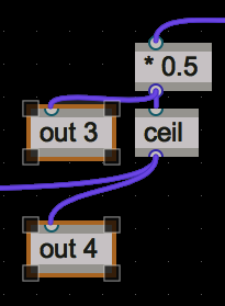
So the point that I have labelled as 'J' previously is now connected to an added 'out' object: 'out3' in this case, and the 'K' point is connected to 'out4'. In the Max environment, then we just use scope~ objects to see what the waveforms look like:

The 'out3' output shows the sawtooth waveform output of the phasor object, and so is connected to a 'scope~' object so we can see what it looks like. (I then turned this into the diagrams used earlier).
The 'out4' output is also connected to a number box, so that I can double-check that the 'ceil' object only outputs 1,2,3 and 4. I didn't show that bit of the Gen code, but there's also an 'out5' being used here, but the scope~ object for that is cropped off the bottom of the screenshot.
So that's how you see what is happening inside the Gen code, and this is one way to debug as you develop your design. When you don't need the debugging any longer, then you just delete all the added 'out
Main timing (envelope)


The timing for the envelopes uses the same phasor object, but this time I wanted to have envelopes lasting half of the step lengths: so 1/8th notes. This is why the phasor is multiplied so that it goes from 0 to 8. You can see this at point C.
If we use the 'wrap' object, then that 0 to 8 sawtooth gets 'wrapped' into the space between 0 and 1, and we get the waveform at point D. This is a sawtooth running at 8 times the bar length, and twice the step sequencer rate: in other words - 1/8th notes. Unfortunately, the 'phasor' object outputs a rising sawtooth, and percussive sounds require a falling sawtooth, so we invert it by multiplying by -1 (the '*-1' object ) to give point E, and then we add 1 to it ( '+ 1' ) to get point F. This is a falling 'ramp' at twice the step sequencer rate, so we need to do some more processing to get four ramps to match the step sequencer.
This is achieved by using the 'ceil' object again, and this turns the unwrapped 0-8 sawtooth into a series of numbers: 1, 2, 3, 4, 5, 6, 7, and 8, and then using the '==1' object to produce a 'gating' signal. The '==1' object is normally 0, and goes high when the input is equal to 1 - hence the '==1'. So by putting four '==' objects in parallel, we can produce gates that go to 1 for the 1st, 3rd, 5th and 7th falling ramps. Using these gates on the falling sawtooth will give us just four 1/8th note falling ramps which are perfect for using as percussive envelopes, and which are locked in sync with the step sequencer - you can see this is you compare all of the points:

So if you look at K, the the four percussive envelopes in H match exactly to the four steps in K.
Note that if you change the '==' numbers, then you can choose different timings for these notes. I will leave it to you to work out the limitations of this approach...
Here's a screenshot from actual debugging during development, showing points B, C, G and H, all output using 'out

LFO and Frequency control

The Expression control (an eternal control pedal plugged into the OWL pedal) is used to control the rate of an LFO that modulates the cut-off frequency of the 'VCF' in the audio section. This time, instead of the phasor object, the 'cycle~' object is a better choice, because it outputs a sine wave, and the smooth waveform is perfect for slow filter modulation. The Expression pedal output (from 0 to 1) is adjusted to a suitable range of rates for the LFO, and the output of the LFO (-1 to +1) is scaled and has an offset added so that it output a sine wave that goes from 0 to 1.
Audio section

The percussive envelope is also used to drive a VCA that envelopes the output of the series of filters. A DC-blocking filter prevents any problems with very low frequencies, and the final output goes to the two main stereo outputs of the OWL pedal: called 'Out1' and 'out2'.
Conclusion
Let's go back to the beginning of this blog, and review the progress. We started by implementing a simple guitar expression/volume pedal, and we ended with a 4-step sequencer driving two detuned sawtooth 'VCOs', into a resonant 'VCF' with an AD envelope and a sine wave LFO driving the cutoff frequency, followed by a 'VCA' driven by an AD envelope. All in a tiny pedal box, and there isn't very much code - there are just 57 of those little Gen object boxes at the op level, and the 'Tap Tempo' adds a few more.For me, the hardest bit was figuring out how to compile the finished code and get it into the OWL pedal, which involves going to the Rebel Technology site and using a web interface. Once you've got the hang of it, that isn't difficult either - and Rebel Technology have lots of video tutorials on YouTube so you can see what to do.
So what was the best bit? Actually, figuring out how to do all of the timing by using phasor-based sawtooth waveforms was my favourite activity. Putting those extra 'out n' objects into the Gen patch and then looking at the waveforms in the outer Max patch was just like probing a circuit with an oscilloscope. Most amazing of all - working at 48 kHz wasn't anywhere near as scary as I expected!
I hope that you have been inspired to consider looking at programming an OWL. There is a lot of information on the Rebel Technology web-site, and the forum is full of people who can help. Have fun!
Links
Things mentioned in this blog posting:Cycling '74 Gen
Mod Devices MOD Duo
Rebel Technology OWL Pedal
Rebel Technology OWL Modular
SynthFest UK
Native Instruments Reaktor
Flintpope
Compelling problems - making things happen in novels
Hello World!